









Abstract
The LISUN SW Series Power Cord Flexibility Bending Tester represents a significant advancement in high-precision power cord flexibility testing, delivering automated cycle counting with exceptional repeatability for cable endurance validation. This article examines the technical architecture of the SW-1, SW-2, and SW-6 models, focusing on their PLC-based control systems, servo motor actuation, and current-based failure detection mechanisms. These instruments enable R&D and quality control professionals to conduct bending tests in strict accordance with IEC 60884-1, IEC 60745-1, and GB/T 2099.1 requirements. By integrating multi-station configurations with programmable test parameters and automatic shutdown upon specimen failure, the SW Series provides a robust solution for validating power cord reliability across household appliances, power tools, and component manufacturing applications. The article presents comparative performance data, operational principles, and practical implementation guidance for optimizing cable flexibility testing protocols.
1.1 PLC-Based Control and Precision Timing
The LISUN SW Series power cord bending tester employs a programmable logic controller (PLC) as its central processing unit, enabling precise control over bending cycle frequency, count accuracy, and test sequencing. The PLC generates consistent timing signals that govern the servo motor’s reciprocating motion, ensuring each bending cycle is executed with identical angular displacement and velocity profile. This deterministic control architecture eliminates timing drift commonly observed in relay-based systems, achieving cycle count repeatability within ±0.1% of the programmed value. The automated cycle counting function records every completed bend, storing cumulative data in non-volatile memory for post-test analysis and compliance documentation.
1.2 Servo Motor Drive and Load Application
Precision torque transmission is achieved through a servo motor coupled to the test station’s bending arm. Unlike conventional induction motors, the servo drive provides closed-loop feedback on angular position and speed, allowing the system to maintain consistent bending angle (±1°) even when testing cables with varying mechanical resistance. The servo motor’s dynamic response enables acceleration profiles that replicate real-world flexing conditions, while the integrated encoder provides real-time position data to the PLC for cycle validation. This electromechanical synergy ensures that the power cord flexibility tester applies uniform mechanical stress across all test specimens, regardless of individual cable stiffness variations.
2.1 Comparative Analysis of SW-1, SW-2, and SW-6 Models
The SW Series offers three distinct configurations to accommodate varying laboratory throughput requirements. The SW-1 single-station system suits low-volume validation testing, while the SW-2 dual-station configuration doubles productivity for comparative material analysis. The SW-6 six-station model addresses high-throughput production quality control, enabling simultaneous testing of multiple cable samples under identical environmental and electrical conditions. Each test station operates independently, allowing mixed-specimen testing without cross-interference. This modular approach enables laboratories to maximize equipment utilization while maintaining stringent test integrity across all channels.
| Parameter | SW-1 Single Station | SW-2 Dual Station | SW-6 Six Station | IEC 60884-1 Minimum Requirement |
|---|---|---|---|---|
| Test Stations | 1 | 2 | 6 | 1 |
| Bending Angle Range | 10°–90° (adjustable) | 10°–90° (adjustable) | 10°–90° (adjustable) | 45°±5° |
| Bending Frequency | 5–60 cycles/min | 5–60 cycles/min | 5–60 cycles/min | 10 cycles/min |
| Load Current Range | 0.1–50A per station | 0.1–50A per station | 0.1–50A per station | Rated current |
| Cycle Count Capacity | 0–999,999 | 0–999,999 | 0–999,999 | ≥10,000 |
| Voltage Supply | AC 220V/50Hz | AC 220V/50Hz | AC 220V/50Hz | Rated voltage |
2.2 Independent Station Control and Data Acquisition
Each test station within the multi-station configurations features autonomous control logic, enabling individualized start/stop commands, separate cycle counters, and independent failure detection. This distributed architecture prevents a single specimen failure from interrupting ongoing tests on other stations, maximizing operational efficiency. The data acquisition system logs station-specific parameters—including instantaneous load current, cycle progression, and failure events—into timestamped records. Quality engineers can retrieve these datasets for statistical process control analysis, identifying production trends or material inconsistencies across different cable batches.
3.1 Load Current Monitoring Principle
A fundamental requirement for power cord flexibility testing involves maintaining electrical continuity throughout mechanical bending. The SW Series implements a current-based judgment system that continuously monitors the load current flowing through each test specimen. When the bending action causes conductor breakage or intermittent contact, the current deviates from the predetermined threshold, triggering an immediate response. The system categorizes failures into two distinct modes: complete conductor fracture and partial breakage exhibiting intermittent conductivity. The PLC evaluates current waveform characteristics, distinguishing between acceptable transient variations and genuine fault conditions, thereby minimizing false-positive detections during normal test operation.
3.2 Automatic Test Termination and Alarm Notification
Upon detecting a failure condition, the power cord bending tester executes an automatic stop sequence, terminating the cycling action for the specific station while preserving accumulated test data. An audible alarm and visual indicator alert operators to the failed specimen, enabling prompt inspection and documentation. The automatic shutdown capability prevents continued cycling on damaged cables, which could skew test results or create unsafe operating conditions due to exposed conductors. For unattended long-duration testing, the system’s fault memory retains the exact cycle count at which failure occurred, providing precise data points for Weibull analysis or lifetime prediction models.
4.1 IEC 60884-1 and GB/T 2099.1 Alignment
The SW Series power cord flexibility tester is engineered to satisfy the mechanical endurance requirements specified in IEC 60884-1 Clause 23 and its Chinese counterpart GB/T 2099.1. These standards mandate that plugs and socket-outlets withstand a defined number of bending cycles without exhibiting conductor damage or unacceptable temperature rise. The tester’s adjustable bending angle (up to 90°) and frequency range (up to 60 cycles per minute) accommodate the standard’s prescribed test conditions, which typically require 10,000 cycles at a 45° bending angle. The automated cycle counting capability ensures precise adherence to the required test count, eliminating manual counting errors that could compromise compliance certification.
4.2 IEC 60745-1 and IEC 60335-1 Integration
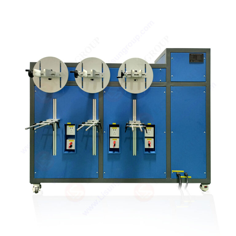
For power tools and household appliances, the cable bending test forms part of the broader type-testing protocol defined in IEC 60745-1 and IEC 60335-1. These standards address flexible cord endurance under repeated flexing during normal equipment operation. The SW Series supports the specific test conditions outlined in these standards, including defined bending rates, load application, and duration parameters. By accommodating the distinct requirements across multiple standards, this cable flexibility testing equipment serves as a versatile platform for manufacturers producing goods for international markets with divergent regulatory frameworks. Laboratories can configure test profiles for each standard and store them for rapid recall during certification testing.
5.1 Bending Angle, Frequency, and Count Programmability
The power cord bending tester provides comprehensive programmability, allowing operators to define bending angle (10°–90°), cycling frequency (5–60 cycles/min), and target cycle count. These parameters are entered via the touchscreen interface or external control software, with real-time display of current values during test execution. The ability to program non-standard test conditions enables R&D teams to conduct accelerated aging studies or simulate specific application scenarios beyond regulatory minimums. For example, automotive electronics manufacturers may implement 90° bending angles at elevated frequencies to replicate severe cable routing conditions in vehicle applications, generating reliability data that informs design improvements.
5.2 Sample Fixturing and Load Configuration
Proper specimen mounting is critical for reproducible bending tests, ensuring that the flexing zone corresponds to the cable’s actual service stress point. The SW Series provides adjustable gripping fixtures that accommodate cable diameters from 5mm to 20mm, with precise positioning mechanisms to maintain consistent bend radius. The load circuit configuration enables series connection of resistive or electronic loads, establishing the specified test current through each specimen. Operators can configure different loads across stations, facilitating simultaneous testing of cables with different current ratings. This flexibility proves particularly valuable for component suppliers producing diverse product lines with varying electrical specifications.
6.1 Test Setup and Calibration Procedure
Achieving accurate test results requires proper equipment setup following a structured calibration protocol. Before initiating a test run, technicians must verify the bending angle using the integrated measurement scale or external protractor, confirm the servo motor’s zero position, and calibrate the load current monitoring circuit against a reference ammeter. The PLC self-check routine validates sensor functionality and actuator response, identifying potential system faults before mechanical cycling begins. This pre-test verification ensures that the automated cycle counting function operates from a known baseline, enabling precise determination of failure points during the test.
6.2 Data Logging, Export, and Traceability
The SW Series transmits test data to connected PC workstations via RS-232 or USB interfaces, enabling comprehensive documentation and traceability. The data management software generates test reports containing specimen identification, test parameters, cycle progression, failure signatures, and timestamps. This information supports ISO/IEC 17025 quality system requirements for testing laboratories, providing complete audit trails for certification bodies. Batch testing data aggregation enables statistical analysis of production consistency, with control charts highlighting variations in cable bending life across different manufacturing runs. The integration of automated cycle counting with structured data management transforms raw test results into actionable engineering insights.
7.1 Household Appliance and Power Tool Manufacturing
Manufacturers of washing machines, vacuum cleaners, electric kettles, and handheld power tools integrate the SW Series into their incoming material inspection and final product validation workflows. For incoming cable inspection, quality control departments execute abbreviated bending tests on incoming batches, establishing baseline reliability data for supplier qualification programs. During product development, R&D teams employ the multi-station configuration to compare cable designs, testing different conductor gauges, insulation materials, and strain relief geometries under identical conditions. This comparative testing accelerates design optimization by identifying marginal cable constructions that fail early during automated cycle counting.
7.2 Component Suppliers and Third-Party Laboratories
Plug and socket manufacturers utilize the bending tester to validate cord sets and cord connectors against the mechanical endurance requirements of their product certifications. Independent testing laboratories leverage the SW-6 configuration to process multiple client samples simultaneously, maximizing throughput while maintaining the precision required for accredited testing. The equipment’s compliance with international standards, combined with reliable failure detection, positions these laboratories to provide authoritative test reports that withstand regulatory scrutiny. The automated cycle counting technology ensures that reported test results accurately reflect the number of applied bending cycles, supporting the credibility of certification claims made by product manufacturers.
The LISUN SW Series Power Cord Flexibility Bending Tester delivers a compelling combination of automated cycle counting, multi-station versatility, and regulatory compliance capability that directly addresses the validation needs of cable and appliance manufacturers. Its PLC-controlled servo drive system ensures precise mechanical execution of bending protocols, while the current-based failure detection mechanism provides immediate and accurate identification of conductor faults. The equipment’s support for approximately six different test configurations—spanning single-station development work through six-station production testing—enables laboratories to scale their operations according to evolving demand. By aligning with IEC 60884-1, IEC 60745-1, IEC 60335-1, and GB/T 2099.1, this power cord bending tester enables organizations to generate reliable endurance data that supports certification, quality assurance, and continuous product improvement. For technical professionals seeking to enhance their cable reliability validation capabilities, the SW Series represents a technically sound investment that yields long-term operational benefits.
Q1: How does the automated cycle counting system ensure accuracy during long-term bending tests?
A: The LISUN SW Series employs a PLC-based counting system that receives positional feedback from the servo motor’s encoder at every cycle completion. Each time the bending arm returns to its home position, the PLC increments the cycle counter by one unit, ensuring that the recorded count directly corresponds to actual mechanical motion. This encoder-based verification prevents miscounting that could occur in systems relying solely on timing calculations, particularly when variations in cable stiffness affect motor speed. For extended testing exceeding 100,000 cycles, the system maintains count accuracy through non-volatile memory storage, preserving data even during brief power interruptions. This precision in automated cycle counting provides confidence that test termination occurs exactly at the programmed specification, regardless of test duration.
Q2: What is the recommended maintenance schedule for the SW Series to ensure consistent test results?
A: To maintain the calibration integrity of the power cord flexibility tester, monthly preventive maintenance is recommended, focusing on mechanical components and electrical verification. Technicians should inspect the bending arm pivots for bearing wear and apply manufacturer-approved lubricant every 500 operating hours. The load current monitoring circuit should be cross-checked against a calibrated reference ammeter weekly, with sensor drift corrections performed through the PLC calibration menu. Every quarter, the servo motor’s angular positioning accuracy should be validated using a digital protractor, with acceptable deviation limited to ±0.5°. Consumable wear components, including specimen clamping pads and pivot bushings, should be replaced when visual inspection reveals degradation exceeding 20% of original dimensions. Adherence to this schedule ensures that automated cycle counting and failure detection functions continue operating within specification.
Q3: Can the SW Series be used for testing cables with non-standard connectors or custom terminations?
A: Yes, the SW Series flexibility tester accommodates custom cable assemblies through its adjustable fixture system. The gripping mechanism accepts cable diameters from 5mm to 20mm, with interchangeable inserts available for specialized connector geometries. For non-standard terminations, operators can fabricate mounting adapters using the fixture base’s standard bolt pattern. However, it is essential to ensure that the custom mounting does not restrict the cable’s natural bending motion at the specified flexing zone. For testing cables with integrated connectors, the connector housing should be securely fixed to avoid mechanical stress concentration at solder joints. The load current circuit can be configured for any termination type, provided that the electrical connection exhibits resistance below the threshold for triggering false failure detection.
Q4: How does the current-based failure detection distinguish between genuine conductor fractures and connector contact noise?
A: The LISUN SW Series implements a sophisticated signal processing algorithm within the PLC to differentiate failure modes. Genuine conductor fractures typically manifest as a complete loss of current (drop to zero) or a permanent decrease below the programmed threshold. In contrast, connector contact noise appears as brief current interruptions lasting less than 100 milliseconds, often recurring with the bending cycle’s periodic motion. The system incorporates a digital filter that requires the current to remain below 50% of the set value for at least 200 milliseconds before confirming a failure condition. Additionally, the system analyzes the failure signature over multiple bending cycles, distinguishing intermittent contact (which produces discontinuity during only certain bending angles) from permanent conductor separation. This discrimination capability reduces false alarms while ensuring genuine failures trigger the automatic stop function.
Q5: What certifications or calibration documentation are provided with the LISUN SW Series?
A: Each SW Series power cord flexibility tester ships with a factory calibration certificate demonstrating traceability to national metrology standards. This certificate documents the measured accuracy of the bending angle, cycle counting, and load current monitoring systems, along with the ambient conditions during calibration. The equipment is designed to meet the general requirements of IEC 60884-1 for test equipment accuracy, maintaining specified tolerances within a temperature range of 15°C to 35°C. For laboratories requiring accredited calibration, the calibration data supports the setup of an in-house calibration procedure aligned with ISO/IEC 17025 requirements, enabling the equipment to be integrated into the laboratory’s quality management system with documented measurement uncertainty.