Abstract
Switch durability life testing is a critical procedure for validating the mechanical and electrical longevity of switches, plugs, and sockets used in household and industrial applications. This article provides a comprehensive technical guide on performing switch durability life testing using the LISUN CZKS-3 series automated test systems. The primary focus is on understanding test methodologies, standard compliance requirements, and practical implementation steps for evaluating electrical fatigue failure under repeated actuation cycles. Professionals in quality control, product certification, and component manufacturing will gain actionable insights into configuring test parameters, interpreting results, and ensuring compliance with international standards such as IEC 60884-1 and IEC 60669-1. The LISUN CZKS-3 series offers precise PLC-controlled cylinder-driven actuation, enabling repeatable and accurate durability assessments for diverse switch types.
1.1 Definition and Importance of Switch Durability Testing
Switch durability life testing evaluates the ability of electrical switches to withstand repeated mechanical actuation and electrical load cycles without failure. This test simulates years of real-world usage within a compressed time frame, identifying potential failure modes such as contact wear, spring fatigue, arcing damage, and insulation degradation. For manufacturers, passing durability testing is mandatory for product certification according to IEC 61058-1 and related standards, which specify minimum cycle counts ranging from 10,000 to 100,000 operations depending on the switch classification.
1.2 Key Failure Mechanisms in Switch Life Cycles
Electrical fatigue failure in switches manifests through several distinct mechanisms. Contact adhesion occurs when microscopic welding bonds the contacts together under high current during closure. Material transfer between contacts leads to pitting and surface roughness, increasing contact resistance over successive cycles. Mechanical wear of actuation springs reduces contact pressure, potentially causing intermittent open circuits. Arcing during break operations erodes contact material and can degrade nearby insulating surfaces. Understanding these failure modes guides the selection of test parameters in the LISUN CZKS-3 series, which can apply controlled current and voltage conditions during each operating cycle.
1.3 Overview of International Testing Standards
Multiple standards govern switch durability life testing. IEC 60884-1 covers plugs and socket-outlets for household use, specifying 10,000 mechanical operations and 5,000 electrical operations with rated current. IEC 60669-1 addresses switches for household fixed installations, requiring 40,000 operations for electronic switches. IEC 61058-1 provides general requirements for switches, including endurance testing with inductive loads. GB/T 2099.1 represents the Chinese national standard for plugs and sockets, closely aligned with IEC 60884-1. Each standard defines specific test conditions, including ambient temperature, voltage levels, current magnitudes, and operating frequency.
2.1 System Architecture and Core Components
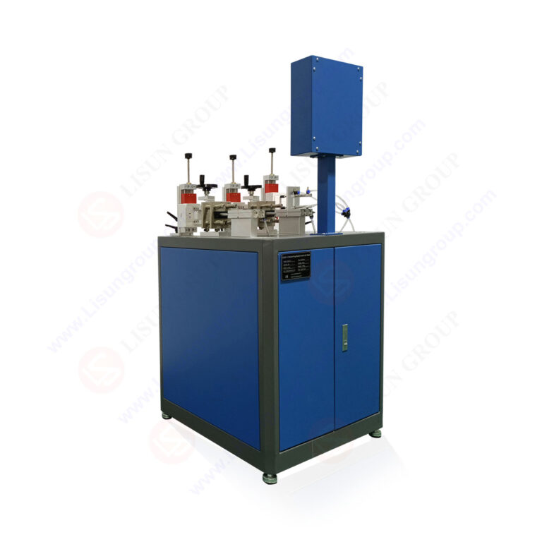
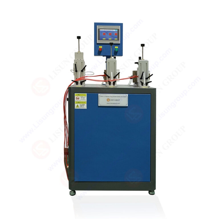
The LISUN CZKS-3 series comprises modular automated test systems designed for switch durability life testing. The core architecture includes a PLC-controlled main unit, pneumatic actuation assemblies, power supply modules, and data acquisition electronics. The CZKS-3 base model supports single-station testing, while the CZKS-3P variant offers multi-position capability for simultaneous evaluation of multiple specimens. The CZKS-3S integrates advanced sensing for contact resistance monitoring during operation, and the CZKS-3A adds automated load switching for compliance with breaking capacity requirements. Each system uses cylinder-driven linear actuation with adjustable stroke length and force, ensuring consistent mechanical input across thousands of cycles.
2.2 Technical Specifications Comparison
The following table presents key technical parameters for the LISUN CZKS-3 series variants:
| Parameter | CZKS-3 | CZKS-3P | CZKS-3S | CZKS-3A |
|---|---|---|---|---|
| Test Stations | 1 | 3 | 1 | 2 |
| Max Operating Cycles (per station) | 100,000 | 100,000 | 100,000 | 100,000 |
| Actuation Stroke Range | 5-30 mm | 5-30 mm | 5-30 mm | 5-30 mm |
| Actuation Force Range | 2-50 N | 2-50 N | 2-50 N | 2-50 N |
| Contact Resistance Measurement | Optional | Optional | Integrated (±0.1 mΩ) | Optional |
| Load Current Range | 0.1-16 A | 0.1-16 A | 0.1-16 A | 0.1-32 A |
| Test Speed (cycles per minute) | 10-60 | 10-60 | 10-60 | 10-30 |
| Data Logging Interface | RS-232 | RS-232, Ethernet | Ethernet, USB | Ethernet, USB |
2.3 Variant Selection Criteria for Different Applications
Selecting the appropriate LISUN CZKS-3 variant depends on the specific testing requirements. For high-volume production quality control, the CZKS-3P with three independent stations maximizes throughput while maintaining individual cycle counting and failure detection per specimen. Laboratories conducting research on contact phenomena benefit from the CZKS-3S’s integrated contact resistance measurement, which captures real-time changes in electrical performance throughout the test duration. The CZKS-3A is specifically designed for breaking capacity testing per IEC 60884-1 Clause 21, accommodating higher load currents and incorporating safety interlocks for arc suppression monitoring.
3.1 Specimen Preparation and Mounting
Proper specimen preparation ensures test validity and repeatability. For switch durability life testing, each specimen must be clean, free from manufacturing debris, and mounted according to its intended orientation. The LISUN CZKS-3 series provides adjustable mounting brackets that accommodate various switch form factors, including rocker switches, push-button switches, toggle switches, and rotary switches. Specimens should be connected to the test system using the appropriate gauge wiring to handle the specified test current without additional voltage drop. All connections must be torque-secured to prevent loosening during extended testing.
3.2 Parameter Configuration via PLC Interface
The PLC control interface on the CZKS-3 series allows operators to define comprehensive test programs. Key configurable parameters include actuation stroke length (typically set to match the switch’s full travel distance plus 1-2 mm overtravel), actuation force (adjusted to simulate typical human operation without exceeding the switch’s mechanical limits), operating speed, and dwell time between actuations. For electrical endurance testing, the system also configures load current, voltage, power factor, and the switching sequence (make-first-break-last or break-first-make-last) depending on the relevant standard requirement.
3.3 Load Circuit Design and Safety Considerations
Designing the load circuit requires careful attention to the switch’s rated conditions. Resistive loads simulate basic incandescent lamp circuits, while inductive loads with power factors of 0.6-0.7 represent motor or ballast applications. The LISUN CZKS-3A includes integrated resistive-inductive load banks that automatically adjust during cycling. Safety considerations include overcurrent protection for the test circuit, emergency stop functionality, and enclosure shielding to contain potential arc flash events. The system’s PLC monitors for abnormal conditions and automatically halts testing if contact welding or open-circuit failures are detected, protecting both the specimen and test equipment.
4.1 Mechanical Endurance Testing Protocol
Mechanical endurance testing evaluates the switch’s ability to withstand repeated actuation without electrical load. This test isolates purely mechanical failure modes such as spring fatigue, housing cracking, and actuator wear. The LISUN CZKS-3 series performs mechanical endurance testing by cycling the switch at its maximum rated speed for the specified cycle count. Operators monitor for audible changes in actuation sound, increased operating force, or visible damage to the switch body. The test is considered passed if the switch completes all cycles without mechanical failure and continues to meet dimensional and force requirements after completion.
4.2 Electrical Endurance Testing Under Load
Electrical endurance testing combines mechanical actuation with electrical load, replicating real-world operating conditions. For each cycle, the switch makes and breaks the circuit under specified voltage and current. The LISUN CZKS-3S with integrated contact resistance measurement provides continuous monitoring of electrical performance. Key parameters tracked include contact resistance fluctuations, arcing duration, and voltage drop across closed contacts. Per IEC 61058-1, electrical endurance tests often require 50,000 to 100,000 cycles depending on the switch category. The system automatically records any instance where contact resistance exceeds a defined threshold, indicating potential failure.
4.3 Breaking Capacity and Making Capacity Verification
Breaking capacity testing, defined in IEC 60884-1 Clause 21 for socket-outlets, verifies the component’s ability to safely interrupt specified fault currents. The LISUN CZKS-3A is specifically designed for this application, applying a high-current load that the switch must break without sustaining damage or creating sustained arcing. Making capacity testing evaluates the ability to close onto a fault current without contact welding. These tests typically involve fewer cycles (10-50 operations) but at significantly higher currents than normal endurance testing. The system records arc duration, peak current, and fault clearance time for compliance documentation.
5.1 Real-Time Monitoring and Data Logging
The LISUN CZKS-3 series provides comprehensive real-time monitoring across all active test stations. Each actuation cycle generates data points including operation count, actuation force measured by load cell, contact resistance, and actuation timing. The CZKS-3S and CZKS-3A variants stream this data via Ethernet connection to a PC running the proprietary LISUN analysis software. Operators can view trend graphs showing progressive changes in contact resistance over thousands of cycles, identifying early warning signs of contact degradation before catastrophic failure occurs. Data logging frequency is configurable from every cycle to periodic sampling at specified intervals.
5.2 Statistical Analysis of Test Results
Statistical methods enhance the interpretation of switch durability life testing results. Weibull analysis is commonly applied to failure data from multiple specimens, providing parameters such as characteristic life (eta) and shape factor (beta). A shape factor above 1.0 indicates increasing failure rate over time, characteristic of wear-out failures. Below 1.0 suggests infant mortality failures. The LISUN software automatically calculates these parameters from test data, generating probability plots and confidence intervals. For qualification testing per IEC 60669-1, manufacturers may need to demonstrate a minimum of 90% survival probability at the specified cycle count with 95% confidence.
5.3 Failure Mode Identification and Classification
When failures occur during testing, systematic classification aids root cause analysis. Common failure modes in switch durability life testing include contact welding (identified by inability to break the circuit or measured current flow in the open state), excessive contact resistance (exceeding the standard’s specified limit, typically 100 mΩ increase over initial value), mechanical jamming (actuation force exceeding 150% of initial value), and insulation breakdown (measured by dielectric withstand test after endurance). The LISUN CZKS-3S with integrated measurement capability automatically flags these failure modes and pauses testing for operator inspection.
6.1 Mapping Test Parameters to IEC Standards
Aligning test programs with specific standard requirements ensures regulatory acceptance. For IEC 60884-1 compliance, the LISUN CZKS-3 series configures tests at rated voltage and 1.25 times rated current for electrical endurance, with a power factor of 0.6 ± 0.05 for inductive loads. IEC 60669-1 requires 40,000 operations at rated voltage for electronic switches, with operating frequency not exceeding 30 cycles per minute to prevent overheating. IEC 61058-1 categorizes switches by operating class (microgap, sub-microgap) and load type (resistive, inductive, motor), each requiring specific test conditions that the CZKS-3 series can accommodate through programmable parameters.
6.2 Documentation and Test Report Generation
Comprehensive documentation is essential for certification audits. The LISUN CZKS-3 series generates detailed test reports including specimen identification, test parameters, cycle-by-cycle data logs, failure event records, and pass/fail determination based on standard criteria. Reports include time-stamped entries for any operator interventions, environmental conditions recorded by integrated sensors, and photographic evidence of specimen condition before and after testing. The system exports reports in PDF and CSV formats, compatible with major certification body documentation systems.
6.3 Calibration and Validation Requirements
Maintaining the test system’s measurement accuracy requires regular calibration. Recommended calibration intervals for the LISUN CZKS-3 series include annual verification of actuation force sensors against certified weights, semi-annual contact resistance measurement validation using calibrated precision resistors, and quarterly load bank performance verification using calibrated power analyzers. System validation using reference specimens with known failure characteristics should be performed after any hardware modification or firmware update. Calibration records must be maintained as part of the quality management system for compliance with ISO/IEC 17025 laboratory accreditation requirements.
7.1 Household Switch and Socket Testing
Household applications represent the most common use case for the LISUN CZKS-3 series. Testing wall switches according to IEC 60669-1 requires cycling at 10-20 operations per minute with resistive and inductive loads simulating typical lighting circuits. Socket testing per IEC 60884-1 involves inserting and withdrawing a test plug under load, measuring withdrawal force after endurance, and verifying that socket contacts maintain adequate retention force. The CZKS-3P’s multi-station capability enables parallel testing of different switch models or socket designs, accelerating qualification programs for product families.
7.2 Automotive Component Durability Verification
Automotive switches face unique durability challenges including vibration, temperature extremes, and DC load switching with inductive components such as relays and solenoids. The LISUN CZKS-3 series adapts to automotive testing by incorporating DC load banks and programmable dwell times that simulate pulsed operation typical of automotive applications. Testing per automotive manufacturer specifications often requires 100,000 to 500,000 cycles under 12V or 24V DC loads with specified inductive time constants. The system’s PLC-controlled actuation allows programming of complex duty cycles that mirror actual vehicle usage patterns.
7.3 Industrial and Commercial Switchgear Evaluation
Industrial switches and contactors require testing at higher current levels and with more severe load conditions. The LISUN CZKS-3A with 32 A load capacity supports testing of industrial-grade switches covered by IEC 60947 series standards. These tests incorporate short-circuit making and breaking tests at reduced cycle counts but with peak currents up to 10 times rated current to verify arc extinction capability. The CZKS-3A includes arc detection sensors that automatically halt testing if duration exceeds specified limits, protecting both the test article and surrounding equipment from arc flash damage.
Switch durability life testing is an indispensable process for ensuring the reliability and safety of electrical switches, plugs, and sockets across household, automotive, and industrial applications. The LISUN CZKS-3 series provides a comprehensive solution that addresses the full spectrum of testing requirements defined by international standards including IEC 60884-1, IEC 60669-1, and IEC 61058-1. With variants from the standard CZKS-3 to the advanced CZKS-3A with breaking capacity verification, these systems offer the precision, flexibility, and data acquisition capabilities necessary for rigorous compliance testing. The integration of PLC-controlled cylinder-driven actuation, real-time contact resistance monitoring, and automated failure detection enables manufacturers to achieve consistent, repeatable test results while reducing operator intervention and human error. By enabling thorough electrical fatigue failure analysis and providing detailed documentation for certification audits, the LISUN CZKS-3 series empowers quality control engineers to validate product longevity, identify design weaknesses, and ensure that switches meet regulatory requirements before market introduction. Investment in automated switch durability life testing represents a critical step toward delivering reliable, safe electrical components that perform as expected throughout their intended service life.
Q1: What is the difference between mechanical endurance and electrical endurance testing for switches?
A: Mechanical endurance testing evaluates the switch’s physical components—springs, actuators, housing—by cycling the switch without any electrical load applied. This test isolates purely mechanical failure modes such as spring fatigue, bearing wear, and housing cracking. Electrical endurance testing combines mechanical actuation with specified voltage and current loads, simulating real-world operating conditions. During electrical testing, the switch must make and break the circuit under load, exposing contacts to arcing, material transfer, and thermal stress. IEC 60884-1 typically requires 10,000 mechanical operations and 5,000 electrical operations for socket-outlets. The LISUN CZKS-3 series supports both test types, with the CZKS-3S variant providing integrated contact resistance monitoring essential for detecting electrical degradation during endurance testing.
Q2: How do I select the appropriate LISUN CZKS-3 variant for my testing laboratory?
A: Selection depends on your specific testing requirements and specimen volume. The basic CZKS-3 is suitable for low-volume testing of standard switches with one station and optional contact resistance measurement. For production quality control where multiple specimens must be tested simultaneously, the CZKS-3P offers three independent stations, increasing throughput by up to 300 percent. If your work involves research into contact phenomena or requires detailed electrical performance tracking, the CZKS-3S with integrated contact resistance measurement provides continuous monitoring with 0.1 milliohm resolution. For laboratories conducting breaking capacity verification per IEC 60884-1 Clause 21, the CZKS-3A supports higher load currents up to 32 A and includes advanced safety interlocks. Consider your typical test standards, required cycle counts, and budget constraints when selecting, and consult LISUN’s technical support for application-specific recommendations.
Q3: What are the common causes of premature switch failure during durability testing, and how can they be identified?
A: Premature failures during switch durability life testing often result from contact welding, excessive contact resistance rise, mechanical jamming, or insulation breakdown. Contact welding occurs when high inrush currents create localized melting at contact points, causing permanent adhesion. This failure is identified when the switch fails to break the circuit, indicated by continuous current flow in the open position. Excessive contact resistance typically manifests as voltage drop exceeding standard limits, often caused by material transfer, oxidation, or reduced contact pressure from spring fatigue. The LISUN CZKS-3S continuously monitors contact resistance and flags increases beyond programmable thresholds. Mechanical jamming is detected by actuation force sensors that measure force required for each cycle; a 50 percent increase over baseline indicates pending mechanical failure. Insulation breakdown requires dielectric withstand testing after endurance completion. Analyzing failure patterns across multiple specimens using the system’s data logging capability helps identify root causes and guides design improvements.
Q4: How often should the LISUN CZKS-3 series test system be calibrated, and what does the calibration process involve?
A: Regular calibration ensures measurement accuracy and compliance with ISO/IEC 17025 requirements. LISUN recommends annual calibration of actuation force sensors using certified calibration weights traceable to national standards, with acceptance criteria of ±1 percent of reading for forces between 2 N and 50 N. Contact resistance measurement circuits should be validated semi-annually using calibrated precision resistors at 10 milliohm, 100 milliohm, and 1 ohm values, with acceptance within ±0.5 percent of reading. Load bank performance, including current and power factor accuracy, requires quarterly verification using a calibrated power analyzer. The calibration process involves connecting reference standards to the system’s measurement inputs, recording output readings, and adjusting offsets or gain factors within the PLC software if deviations exceed tolerance. Detailed calibration records must document all adjustments and include before-and-after measurement data. LISUN provides calibration certificates and procedures, and authorized service centers offer on-site calibration services to minimize downtime.
Q5: What data analysis features does the LISUN CZKS-3 series provide for evaluating test results?
A: The LISUN CZKS-3 series, particularly the CZKS-3S and CZKS-3A variants with Ethernet connectivity, provides comprehensive data analysis through proprietary PC software. Real-time trending displays show contact resistance, actuation force, and operating time versus cycle count, allowing operators to identify degradation patterns as they develop. The software automatically generates Weibull distribution plots from failure data, calculating parameters such as characteristic life (eta) and shape factor (beta) with confidence intervals for statistical analysis. Histogram views show the distribution of measurement values across the test population, highlighting outliers and process variability. Pass/fail determination is automated based on user-defined limits consistent with applicable standards. Final test reports include summary statistics, graphical trend data, failure event logs with timestamps, and specimen condition documentation. Data export to CSV format enables further analysis using statistical software packages for detailed reliability engineering studies. The system also supports multi-specimen comparison charts, facilitating side-by-side evaluation of different design iterations or competitor products.