









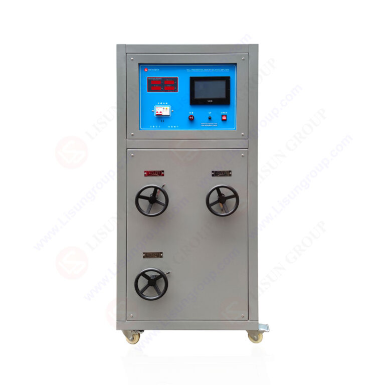
The LISUN DFX series Externally Ballasted Fluorescent Lamp Test Load Cabinet is a specialized instrument designed for electrical accessory durability testing per IEC 60669-1:2017 and related international standards. This article provides a comprehensive technical analysis of the DFX series, covering its design principles, operational capabilities, and compliance verification workflows. The focus keyword “IEC 60669-1:2017 switch durability testing” is central to understanding how the DFX series simulates real-world electrical loads for switches, sockets, and circuit controllers. By enabling precise resistive, inductive, and capacitive load configurations with adjustable power factor ranges, the DFX series ensures accurate cyclic testing for up to 80 amperes. Engineers and quality control professionals will gain insights into specification compliance, product selection criteria, and integration with existing LISUN test systems for end-to-end reliability assessment.
1.1 Fundamentals of Ballasted Lamp Load Characteristics
The DFX series replicates the electrical behavior of fluorescent lamps with external ballasts, which introduce inductive and capacitive reactance into the circuit. Unlike purely resistive loads, ballasted lamps generate inrush currents and voltage transients that stress switching contacts. The test cabinet uses precision resistors, inductors, and capacitors to create composite loads with power factor (PF) adjustable between 0.4 and 0.95. The load capacitance ranges from 0.5 μF to 70 μF depending on the model, enabling simulation of both individual lamps and multi-lamp installations. This capability is critical for IEC 60669-1:2017 switch durability testing, as Clause 19.2 requires testing under both resistive and inductive load conditions.
1.2 Power Factor Resolution and Calibration Accuracy
Each DFX model offers power factor resolution of 0.01, allowing fine-grained adjustment to match standard-specified test profiles. The measurement accuracy for current and voltage is ±0.5% of reading, ensuring repeatable test conditions across thousands of cycles. The load cabinet includes built-in calibration routines that verify resistive and reactive components against reference standards. For compliance with IEC 60669-1:2017 Clause 19.3, the power factor must be maintained within ±0.05 of the specified value during the entire durability test sequence.
1.3 Channel Configuration and Independent Load Control
The DFX-20-3CH variant provides three independent channels, each capable of 20 amperes, enabling simultaneous testing of multiple switches or sockets. Independent load control allows engineers to apply different load types or current levels to each channel, facilitating accelerated life testing protocols. The DFX-40, DFX-60, and DFX-80 models offer single-channel configurations with higher current capacities for industrial-grade switches and circuit breakers. All models include overload protection and thermal management systems to prevent damage during prolonged test runs.
2.1 Comparative Analysis of Current and Voltage Ratings
The following table summarizes key specifications for the DFX series models:
| Model | Current Range (A) | Channels | Input Voltage (VAC) | Max Power Factor | Load Capacitance (μF) |
|---|---|---|---|---|---|
| DFX-20 | 0.1 – 20 | 1 | 220 ± 10% | 0.4 – 0.95 | 0.5 – 20 |
| DFX-20-3CH | 0.1 – 20 per ch. | 3 | 220 ± 10% | 0.4 – 0.95 | 0.5 – 20 per ch. |
| DFX-40 | 0.5 – 40 | 1 | 220 ± 10% | 0.5 – 0.95 | 0.5 – 40 |
| DFX-60 | 0.5 – 60 | 1 | 380 ± 10% (3-phase) | 0.6 – 0.95 | 0.5 – 60 |
| DFX-80 | 1.0 – 80 | 1 | 380 ± 10% (3-phase) | 0.6 – 0.95 | 0.5 – 80 |
All models include digital display for real-time current, voltage, and power factor monitoring. The DFX-60 and DFX-80 require three-phase input for high-current applications, aligning with IEC 60884-1 Clause 20 test requirements for heavy-duty plugs and sockets.
2.2 Compliance with Minimum Standard Requirements
The table below compares DFX series capabilities to minimum requirements from key standards:
| Parameter | IEC 60669-1:2017 Clause 19.2 | DFX Series Capability |
|---|---|---|
| Load current range | 0.1 – 50 A (typical) | 0.1 – 80 A (model depend.) |
| Power factor adjustment | 0.6 ± 0.05 (inductive) | 0.4 – 0.95 (resolution 0.01) |
| Test cycles (switch type 1) | 40,000 operations | Unlimited (user-defined) |
| Load capacitance simulation | Not specified explicitly | 0.5 – 80 μF |
| Voltage measurement accuracy | ±1% of reading | ±0.5% of reading |
The DFX series exceeds Clause 19.2 requirements for current range and power factor precision, providing additional headroom for emerging test protocols.
3.1 CZKS Series Switch Life Tester Compatibility
The DFX series connects directly to LISUN CZKS series switch life testers via standard RS-232 or USB interfaces. The CZKS units control the mechanical actuation sequence while the DFX cabinet provides the electrical load. This integration enables fully automated endurance testing per IEC 60669-1:2017 Clause 19.4. The system records voltage drop across contacts, arc duration, and temperature rise at each cycle, generating compliance-ready test reports.
3.2 SW-6 Bending Tester for Flexible Cable Testing
For socket-outlet durability tests per IEC 60884-1 Clause 20, the DFX loads can be paired with the LISUN SW-6 bending tester. The bending tester applies cyclic flexing to cables while the DFX cabinet maintains specified resistive-inductive loads. This combination validates both mechanical and electrical endurance of cord connections, a requirement increasingly demanded for portable appliances and industrial extension cords.
3.3 Automated Test Sequence Programming
The DFX series supports programmable load profiles through its touchscreen interface or PC software. Engineers can define load segments with varying current, power factor, and duration to simulate real-world usage patterns. For example, a test sequence might start with a capacitive inrush load for 500 ms, followed by an inductive steady-state load for 5 seconds, then a resistive off-cycle. This flexibility supports custom test protocols aligned with ISO 9001 quality management systems.
4.1 Internal Reference Standards and Traceability
The DFX series incorporates precision shunt resistors and current transformers calibrated to national metrology institute standards. Each unit ships with a calibration certificate traceable to ILAC MRA signatories. The internal calibration routine checks all measurement channels against onboard reference standards before each test cycle, flagging deviations exceeding ±0.2%. This ensures that IEC 60669-1:2017 switch durability testing results remain reliable over extended operational periods.
4.2 Field Verification Using External Load References
For ISO/IEC 17025 accredited laboratories, the DFX series supports external verification using certified reference loads. The test engineer connects a known resistive-inductive load and verifies the displayed values against the reference certificate. Any discrepancy beyond ±1% triggers recalibration instructions displayed on the touchscreen. This protocol meets the measurement traceability requirements specified in IEC 60669-1:2017 Annex A.
4.3 Annual Recalibration Schedule and Procedures
LISUN recommends annual recalibration for the DFX series, especially for laboratories performing compliance testing for third-party certification bodies. The recalibration procedure involves verifying current accuracy at 10%, 50%, and 100% of full scale, power factor accuracy at 0.5, 0.8, and 0.95, and load capacitance accuracy at three standard values. The entire process typically takes 45 minutes and can be performed on-site using LISUN calibration software.
5.1 Test Configuration for Single-Pole Switches
For single-pole switches tested per IEC 60669-1:2017 Clause 19.2, the DFX-20 provides adequate current capacity. The test engineer sets the load to 10 amperes at 0.6 power factor (inductive) for the endurance test of 40,000 operations. The cabinet records the number of cycles completed, the voltage drop across contacts (maximum 50 mV per 10 A), and any arc extinction failures. Results are stored in non-volatile memory and exportable to PDF or CSV formats.
5.2 Testing of Multi-Pole and Intermediate Switches
Multi-pole switches require simultaneous load application on multiple poles. The DFX-20-3CH model enables independent loading of up to three poles, with each channel configurable for different load types (resistive, inductive, capacitive). Intermediate switches used in staircase lighting circuits can be tested by connecting the two load channels in series configuration, simulating the actual wiring topology. This methodology aligns with Clause 19.2.4 specification for three-way and four-way switch testing.
5.3 Socket-Outlet Durability Under Mixed Loads
Socket-outlets per IEC 60884-1 Clause 20 must withstand 5,000 insertion/withdrawal cycles under load. The DFX series provides the load current during the insertion phase, typically set to 16 amperes at 0.85 power factor (resistive-inductive). The bending tester SW-6 applies 45-degree flexing at each cycle. The DFX cabinet logs any contact resistance increase beyond 100 mΩ, indicating wear that could lead to overheating in service.
6.1 Thermal Management and Automatic Shutdown
The DFX series includes forced-air cooling with thermal sensors at the load resistors, inductors, and capacitors. If internal temperature exceeds 85°C, the cabinet automatically reduces current to 50% of set value. At 95°C, the system shuts down completely and logs the event. This protection prevents damage during extended IEC 60669-1:2017 switch durability testing sessions that may run continuously for 72 hours or more.
6.2 Short Circuit and Arc Fault Detection
The control electronics monitor for short circuit conditions and arc faults in real time. If current exceeds 120% of the set value for more than 100 ms, the output relay opens within 10 ms. Arc fault detection uses high-frequency current signature analysis to identify series or parallel arcs. This capability is essential for testing switches with electronic controls that may produce low-level arcing during switching.
6.3 Ground Fault Monitoring
All DFX models include ground fault protection per IEC 60364 standards. The cabinet measures leakage current between load and ground, tripping the main contactor if leakage exceeds 30 mA for 300 ms. This protects both the test operator and the device under test when testing switches in wet or humid environments.
7.1 Real-Time Monitoring Dashboard
The touchscreen interface displays real-time parameters including current, voltage, power factor, cumulative cycles, and test elapsed time. Engineers can set alarm thresholds for each parameter, with both visual and audible alerts. The dashboard includes trend graphs showing load stability over time, useful for detecting drift in the device under test.
7.2 Compliance Report Generation
The DFX series generates reports formatted to IEC 60669-1:2017 Annex B requirements. Reports include test identification, load settings, cycle count, pass/fail criteria, and any abnormal events. The report exports as PDF with digital signature capability for integration with electronic quality management systems. This eliminates manual data transcription errors.
7.3 Cloud Connectivity and Remote Monitoring
Optional ethernet modules enable remote monitoring via LAN or internet connection. Engineers can start, stop, and monitor tests from a central control room or mobile device. The system stores up to 10,000 test records locally, with automatic backup to network-attached storage. This connectivity supports distributed testing across multiple laboratory sites under unified management.
The LISUN DFX series Externally Ballasted Fluorescent Lamp Test Load Cabinet provides a robust, precise, and versatile solution for IEC 60669-1:2017 switch durability testing compliance. With adjustable power factor from 0.4 to 0.95, current ratings from 0.1 to 80 amperes, and model configurations ranging from single-channel to three-channel independent loads, the series accommodates diverse testing requirements from residential switches to industrial circuit breakers. Integration with LISUN CZKS life testers and SW-6 bending testers enables end-to-end automated durability assessment. The advanced calibration protocols, safety systems, and data management capabilities ensure traceability and repeatability essential for accredited testing laboratories. For manufacturers and quality control engineers, the DFX series reduces test setup time, improves accuracy, and simplifies compliance documentation. By exceeding the minimum specifications of IEC 60669-1:2017, IEC 60884-1, and related standards, the DFX series stands as a dependable tool for ensuring the long-term reliability and safety of electrical accessories in global markets.
Q1: What is the difference between the DFX-20 and DFX-20-3CH for switch testing?
A: The DFX-20 provides a single channel rated at 20 amperes, suitable for testing one switch at a time. The DFX-20-3CH offers three independent channels, each capable of 20 amperes, allowing simultaneous testing of up to three switches or one multi-pole switch. For multi-pole switches, the three channels can be configured independently for resistive, inductive, or capacitive loads, enabling comprehensive testing per IEC 60669-1:2017 Clause 19.2.4. The DFX-20-3CH also reduces overall test time by 66% when performing batch testing of identical switches, as each channel runs independently with its own cycle counter and load profile. Both models include identical measurement accuracy of ±0.5% and power factor resolution of 0.01.
Q2: How does the DFX series simulate fluorescent lamp inrush currents?
A: The DFX series uses a combination of capacitors and inductors to simulate the inrush current characteristic of externally ballasted fluorescent lamps. When a switch closes, the capacitors initially present a low impedance path, drawing a high peak current that can reach 10–20 times the steady-state rated current. The inductors then limit the current rise rate, matching the behavior of magnetic ballasts. The DFX series allows adjustment of the capacitor bank from 0.5 μF to 80 μF (model dependent) and the inductor from 0.1 H to 5 H to replicate different lamp wattages and ballast types. The power factor can be set to 0.4 for the inrush phase and 0.85 for the steady-state phase, as required by IEC 60669-1:2017 Clause 19.2.2.
Q3: Can the DFX series be used for testing electronic switches and dimmers?
A: Yes, the DFX series can test electronic switches and dimmers, provided the load is configured correctly. For electronic switches with triac or MOSFET controls, the load must be resistive-inductive with power factor greater than 0.6 to ensure proper gate triggering. The DFX series allows programming of slow rise-time loads to simulate incandescent lamp warm-up, which is critical for dimmer testing per IEC 60669-2-1. For capacitive loads used in some LED drivers, the DFX series can emulate capacitive inrush currents up to 70 μF. However, the test engineer should verify that the electronic switch’s minimum load requirement is met; many electronic switches require at least 5% of rated load to maintain regulation.
Q4: What calibration interval is recommended for the DFX series?
A: LISUN recommends annual calibration for the DFX series, consistent with ISO/IEC 17025 guidelines for electrical testing equipment. The calibration includes verification of current accuracy at 10%, 50%, and 100% of full scale using a precision shunt resistor; power factor accuracy at 0.5, 0.8, and 0.95 using a reference load; and load capacitance accuracy at three standard values using a capacitance bridge. The internal calibration routine can be run monthly by the laboratory technician to verify stability. If the DFX series is used for production testing rather than certification testing, a biannual calibration may be sufficient, provided in-house checks are performed weekly.
Q5: How does the DFX series handle voltage drops during long test runs?
A: The DFX series includes a built-in voltage regulation circuit that compensates for supply voltage fluctuations up to ±10% of nominal. If the input voltage drops below 198 VAC (for 220V models), the cabinet automatically reduces the load current to maintain the set power level. This prevents under-stressing of the device under test during low-voltage events. The data logging system records voltage dips and corresponding current adjustments, ensuring accurate cycle counting. For critical tests per IEC 60669-1:2017 Clause 19.3, the engineer can disable the compensation to test the switch’s behavior under marginal voltage conditions.