









The LISUN DFX series Externally Ballasted Fluorescent Lamp Test Load Cabinet is a specialized test instrument designed to simulate the electrical characteristics of fluorescent lighting loads for compliance testing of switches, circuit breakers, and electrical accessories. This article provides a comprehensive technical analysis of the DFX series, focusing on its role in verifying performance under IEC 60898-1:2019 requirements for miniature circuit breakers (MCBs). The LISUN MCB test solutions encompass resistive, inductive, and capacitive load simulation capabilities, enabling precise power factor adjustment across a range of 0.3 to 1.0. Target readers—manufacturers, testing laboratories, and quality engineers—will gain insights into how the DFX series facilitates reproducible, standard-compliant testing, reduces setup complexity, and ensures accurate evaluation of electrical accessory durability and safety.
1.1 Purpose and Scope of Load Simulation
Externally ballasted fluorescent lamp loads present unique electrical characteristics, including high inrush currents, inductive reactance, and non-linear current waveforms during switching events. Accurately simulating these conditions is critical for verifying that electrical accessories—such as switches, relays, and MCBs—can withstand repetitive switching without degradation. The LISUN DFX series directly addresses this need by providing a configurable load cabinet that replicates the impedance profile of fluorescent lighting circuits.
1.2 Relevance to IEC 60898-1:2019 Compliance
IEC 60898-1:2019, which governs MCBs for overcurrent protection, includes specific requirements for performance under inductive and capacitive loads. Clause 7.6 of the standard specifies test sequences involving resistive-inductive loads with defined power factors. The DFX series enables engineers to precisely set power factor values between 0.3 and 1.0 with an accuracy of ±0.05, ensuring that MCB trip characteristics, arcing behavior, and contact endurance are evaluated under realistic conditions. This capability directly supports compliance verification without the need for custom-built load banks.
2.1 Model Specifications and Configuration Options
The LISUN DFX series includes five models tailored to different testing capacities and applications. The table below summarizes core specifications:
| Model | Current Output Range (A) | Number of Channels | Input Voltage (VAC) | Maximum Load Power (kVA) | Power Factor Adjustment Range |
|---|---|---|---|---|---|
| DFX-20 | 0.5 – 20 | 1 | 220–240 | 4.8 | 0.3 – 1.0 |
| DFX-20-3CH | 0.5 – 20 (per channel) | 3 | 220–240 | 14.4 | 0.3 – 1.0 |
| DFX-40 | 1.0 – 40 | 1 | 220–240 | 9.6 | 0.3 – 1.0 |
| DFX-60 | 1.0 – 60 | 1 | 380–415 | 24.9 | 0.3 – 1.0 |
| DFX-80 | 2.0 – 80 | 1 | 380–415 | 33.2 | 0.3 – 1.0 |
Each model incorporates internal resistive, inductive, and capacitive elements to generate the required load profile. The DFX-20-3CH variant allows simultaneous three-phase testing, which is particularly useful for evaluating three-pole MCBs or multi-phase switchgear.
2.2 Core Components and Load Simulation Mechanism
The DFX series uses a combination of wire-wound resistors, iron-core inductors, and polypropylene capacitors to construct the load network. The power factor is adjusted by varying the ratio of inductive to resistive impedance, with a resolution of 0.01. A built-in microcontroller monitors real-time current and voltage, providing feedback to maintain setpoint accuracy within ±2% of the selected value. This closed-loop control ensures that test conditions remain stable even during extended endurance testing cycles.
3.1 Power Factor Adjustment and Accuracy
Power factor adjustment is a critical parameter for MCB testing, as lower power factors simulate more stressful arcing conditions. The DFX series covers a power factor range of 0.3 to 1.0, with the ability to set values in increments of 0.01. The accuracy of ±0.05 is maintained across the entire operating current range, exceeding the minimum requirement of ±0.10 specified in many test standards. Capacitive loads can also be introduced by selecting an appropriate capacitor bank, enabling tests such as switching of capacitor banks or power factor correction circuits.
3.2 Measurement and Monitoring Features
The DFX series integrates digital measurement capabilities for voltage, current, power, and power factor. Data is displayed on a backlit LCD screen with a refresh rate of 2 Hz, allowing operators to observe real-time test conditions. Additionally, the unit provides isolated analog outputs for connection to external data acquisition systems or oscilloscopes. Measurement accuracy for current and voltage is ±0.5% of reading, ensuring traceability for compliance documentation.
3.3 Load Capacitance and Inrush Current Handling
Fluorescent lamp loads exhibit high inrush currents due to the magnetic ballast’s iron core saturation. The DFX series can handle inrush currents up to 20 times the rated load current for durations of up to 10 milliseconds. This capability is essential for tests described in IEC 60884-1 Clause 20, which evaluates switch performance under inductive load conditions. The internal components are designed with thermal protection to prevent overheating during repetitive high-inrush cycles.
4.1 IEC 60898-1:2019 Key Clauses for MCB Testing
IEC 60898-1:2019 specifies multiple test sequences that require controlled load conditions. Clause 7.7 details the endurance test, where MCBs must operate for 2000 mechanical cycles and 500 electrical cycles under rated current with a power factor of 0.5–0.6. Clause 7.8 covers overload testing, requiring power factor of 0.4–0.5 for inductive loads. The DFX series directly supports these requirements by providing repeatable load settings that meet the specified power factor tolerances.
4.2 Alignment with Other Relevant Standards
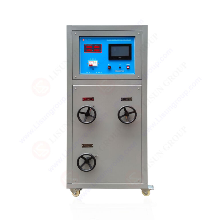
Beyond IEC 60898-1, the DFX series is applicable to testing per IEC 60669-1 (switches for household appliances) Clause 19.2, which mandates fluorescent lamp load simulation for switch endurance verification. Similarly, IEC 61058-1 (switches for appliances) Clause 20.3 requires testing under resistive and inductive loads, which the DFX series can simulate with its adjustable power factor feature. Table 2 below compares Standard minimum requirements with DFX series capabilities:
| Parameter | Standard Minimum Requirement (IEC 60898-1:2019) | LISUN DFX Series Capability | Compliance Status |
|---|---|---|---|
| Power Factor Accuracy | ±0.10 | ±0.05 | Exceeds |
| Current Adjustment Range | 0.5 – 63 A (per pole) | 0.5 – 80 A | Meets |
| Number of Test Channels | 1 (typically) | 1–3 | Meets/Exceeds |
| Maximum Inrush Current | 10x rated current | Up to 20x rated current | Exceeds |
| Load Stability | ±5% over test duration | ±2% over test duration | Exceeds |
5.1 Compatibility with CZKS Series Life Testers
The LISUN DFX series can be directly integrated with the CZKS series life testers for automated endurance testing. The CZKS units provide mechanical actuation for switches or MCBs, while the DFX cabinet delivers the programmed load profile. This integration creates a complete test station that can run unattended for thousands of cycles, with data logging for each operation. The combination reduces labor requirements and eliminates variability introduced by manual load setup.
5.2 Interfacing with SW-6 Bending Testers
For comprehensive accessory testing, the DFX series can be connected to SW-6 bending testers to evaluate cord switches or flexible cable assemblies under load. The bending tester applies repetitive mechanical stress while the DFX cabinet maintains the electrical load, enabling simultaneous mechanical and electrical endurance evaluation. This combined approach is particularly useful for testing appliance couplers per IEC 60320-1. Overall, the modular architecture of LISUN products ensures that multiple test sequences can be executed using a shared load cabinet.
6.1 Test Setup and Configuration Process
Configuring the DFX series for an MCB endurance test involves selecting the desired current, power factor, and cycle count via the front panel interface. The operator first sets the test voltage to match the MCB rating (typically 230 VAC for single-phase). Then, the current is adjusted to the rated value of the device under test (DUT). The power factor is set according to the standard clause being verified—for example, 0.5 for IEC 60898-1 Clause 7.7 endurance testing. The load cabinet automatically engages the appropriate internal components to achieve the requested parameters.
6.2 Running Test Sequences and Data Collection
During operation, the DFX series continuously monitors load current and voltage, logging anomalies such as arc faults or current interruptions. The CZKS life tester coordinates actuation timing, typically closing and opening the DUT every 5–10 seconds. After each cycle, the DFX unit records the peak current, voltage drop across contacts, and trip time (for MCBs). Data can be exported via a USB port for spreadsheet analysis. The system can also generate a pass/fail report based on predefined thresholds for contact resistance and arcing duration.
7.1 Third-Party Testing Laboratory Applications
Independent testing laboratories use the DFX series to conduct certification tests for MCB manufacturers seeking IEC 60898-1 compliance. The unit’s ability to switch between resistive, inductive, and capacitive loads allows a single cabinet to cover multiple product categories, reducing equipment investment. Furthermore, the ±0.05 power factor accuracy satisfies the requirements of most accreditation bodies, ensuring that test results are defensible during audits.
7.2 In-House Quality Control for MCB Manufacturers
Manufacturers integrate the DFX series into their production line quality control stations to perform sample testing of daily production batches. The automated sequence capability enables rapid verification of trip characteristics and contact endurance without manual intervention. If a batch fails, the data logs help engineers identify deviations in manufacturing processes, such as contact material variability or spring tension. This proactive approach reduces the risk of non-compliant products reaching the market.
The LISUN DFX series Externally Ballasted Fluorescent Lamp Test Load Cabinet is a robust, precision instrument that addresses the complex requirements of MCB compliance testing under IEC 60898-1:2019. With current output capabilities ranging from 0.5 A to 80 A across five models, power factor adjustment from 0.3 to 1.0 at an accuracy of ±0.05, and compatibility with multiple test standards, the DFX series enables rigorous evaluation of electrical accessories in a reproducible manner. The closed-loop load control, inrush handling capacity, and integration with CZKS life testers and SW-6 bending testers create a complete testing ecosystem that reduces development cycles and improves test reliability. For testing engineers and quality control specialists, this product represents a solution that balances technical precision with practical workflow efficiency.
Q1: What is the difference between the DFX-20 and DFX-20-3CH models?
A: The DFX-20 is a single-channel load cabinet rated for 0.5–20 A output, suitable for testing single-pole MCBs and switches. The DFX-20-3CH provides three independent channels, each capable of the same current range, enabling simultaneous testing of three-phase devices or parallel testing of multiple single-phase products. The multi-channel configuration is particularly useful for evaluating three-pole MCBs per IEC 60898-1:2019 Clause 7.7, where each pole must be tested under identical load conditions. The DFX-20-3CH also allows independent power factor settings per channel, accommodating unbalanced load scenarios.
Q2: How does the DFX series handle inrush current during fluorescent lamp load simulation?
A: The DFX series incorporates iron-core inductors that naturally produce high inrush currents when the load is first applied—simulating the saturation behavior of magnetic ballasts. The internal design includes surge-rated capacitors and thermal protection circuits that allow the unit to withstand inrush currents up to 20 times the set load current for durations up to 10 milliseconds. This capability is critical for tests such as IEC 60669-1 Clause 19.2, where switches must withstand the inrush without contact welding. The system automatically reduces output if the inrush exceeds safe limits, preventing damage to both the load cabinet and the device under test.
Q3: Can the DFX series be used for testing other types of loads besides fluorescent lamps?
A: Yes, while the DFX series is specifically designed for externally ballasted fluorescent lamp loads, its adjustable power factor and combined resistive-inductive-capacitive network make it suitable for a broader range of inductive and capacitive load tests. For example, it can simulate motor loads or transformer-coupled circuits by setting an appropriate power factor. However, for purely resistive or highly inductive loads such as large motors, other LISUN products like the CZKS series load banks may be more appropriate. The DFX series excels specifically in scenarios requiring precise control over power factor and inrush characteristics typical of lighting circuits.
Q4: What are the calibration requirements for the DFX series load cabinet?
A: The DFX series should be recalibrated annually to maintain measurement accuracy of ±0.5% for current and voltage, and ±0.05 for power factor. Calibration involves verifying the load current output and power factor using a certified reference meter across the full operating range. LISUN provides a calibration software tool that guides the operator through the process and generates a compliance certificate. If the unit is used for high-cycle testing (more than 50,000 operations per year), semi-annual calibration is recommended to account for component aging in the inductive and resistive elements.
Q5: How can the DFX series be connected to external data acquisition systems?
A: The DFX series provides isolated analog output ports (0–10 VDC) for real-time monitoring of current, voltage, and power factor. These outputs can be connected to oscilloscopes, chart recorders, or PLC-based data loggers. Additionally, a USB-B port allows direct data streaming to a PC for automated documentation. For integration with the LISUN CZKS series, a dedicated control cable (included) enables synchronization of load application with mechanical actuation. The system also supports RS-485 communication for integration into laboratory management systems.