









Abstract
The Industrial PLC-Controlled Power Cord Bending Tester, specifically the LISUN SW Series Power Cord Flexibility Bending Tester, provides automated, standards-compliant validation of power cord endurance under repeated flexing stress. Designed for compliance with IEC 60884-1, IEC 60745-1, IEC 60335-1, and GB/T 2099.1, this equipment integrates programmable logic controller (PLC) technology with servo motor drive systems to deliver precise bending cycles, load current monitoring, and automatic failure detection. For R&D and quality control engineers in household appliance manufacturing, hand-held tool production, and plug/socket component testing, the device offers configurable test parameters, multi-station scalability, and real-time current-based judgment. This technical article examines core operating principles, model specifications, application workflows, and practical integration strategies for industrial cable flexibility testing equipment.
1.1 PLC-Controlled Servo Drive Mechanism
The Industrial PLC-Controlled Power Cord Bending Tester employs a closed-loop servo motor system governed by a programmable logic controller. The PLC generates precise motion profiles, controlling the bending arm’s angular displacement, speed, and acceleration. Servo drive feedback ensures positional accuracy within ±0.1 degrees, critical for repeatable bending cycles. The controller accepts user-defined parameters such as bending angle (typically 45° to 180°), oscillation frequency (10 to 60 cycles per minute), and total cycle count (up to 999,999 cycles). This architecture eliminates mechanical drift, maintaining consistent stress application across thousands of cycles without manual recalibration.
1.2 Current-Based Failure Detection System
A dedicated current sensing circuit monitors real-time load current through each test specimen. When a power cord under test experiences conductor breakage, insulation failure, or intermittent contact, the instantaneous current deviation triggers an automatic stop. The system logs the cycle count at failure, enabling engineers to determine mean cycles to failure (MCTF). The detection threshold is adjustable from 0.1 A to 25 A, accommodating various cord gauges and load conditions. This current-based judgment method complies with IEC 60884-1 Clause 23.2 requirements for continuity monitoring during flexibility testing.
1.3 Mechanical Bending Assembly Design
The bending assembly consists of a rotating arm with adjustable pendulum mass, a stationary clamp for cord fixation, and a counterweight balancing mechanism. The cord under test passes through specified bending radii (typically 10 mm to 50 mm, adjustable via interchangeable mandrels). The fixture design minimizes stress concentration at clamp points, distributing bending loads along the cord’s natural flex zone. All contact surfaces use non-abrasive polymer liners to prevent secondary mechanical damage during testing, ensuring failure data reflects intrinsic cord durability rather than test apparatus artifacts.
2.1 IEC 60884-1 Plugs and Socket-Outlets Requirements
The SW Series bending tester directly addresses IEC 60884-1 Clauses 23.2 and 23.3, which mandate flexibility testing for cord anchors and cable entries. The standard specifies a bending angle of 90° ± 1°, a frequency of 60 cycles per minute, and a minimum of 10,000 cycles for normal service. The PLC-controlled system automatically maintains these parameters within tolerance. For cords with rated currents above 6 A, the standard requires a load current equal to 1.25 times the rated current—a condition easily configured via the tester’s programmable load bank. Non-compliance with these clauses can result in product certification rejection by recognized testing bodies.
2.2 IEC 60745-1 Hand-Held Motor-Operated Tools
For power tools, IEC 60745-1 Clause 24.4 specifies bending tests on supply cords at the point of entry into the tool housing. The test requires 10,000 bending cycles at 90° amplitude, with a load current of 1.25 times the tool’s rated current. The SW Series accommodates tool-specific cord diameters up to 18 mm and bending radii down to 10 mm. The inclusion of multi-station configurations (SW-6 with six stations) allows simultaneous testing of six tool samples, reducing qualification time by 83% compared to single-station alternatives. This parallel processing capability is critical for production validation batches.
2.3 IEC 60335-1 Household Appliances Safety
IEC 60335-1 Clause 25.13 requires power supply cord bending tests for appliances with flexible cords. The test protocol involves 10,000 cycles at 5° to 60° per second angular velocity, with the cord loaded to 1.0 times rated current. The SW Series’ adjustable angular velocity range (10 to 60 cycles per minute) directly maps to this requirement. Additionally, Clause 25.14 mandates that cord anchorage must withstand 100 N pull force without displacement—a parameter monitored via the tester’s integrated tension sensor option. The digital logging feature provides traceable records for certification audits.
2.4 GB/T 2099.1 Chinese National Standard Equivalence
GB/T 2099.1, the Chinese national standard equivalent to IEC 60884-1, imposes identical bending test parameters but adds requirements for ambient temperature control (23°C ± 2°C) during testing. The SW Series can be integrated with environmental chambers for temperature-stabilized testing. The standard also mandates that the bending tester must not induce rotational torque on the cord—a condition ensured by the SW Series’ precision-aligned rotation axis and balanced pendulum design. Compliance with GB/T 2099.1 is mandatory for products sold in the Chinese market, making this capability essential for global supply chain qualification.
3.1 SW-1, SW-2, and SW-6 Configuration Analysis
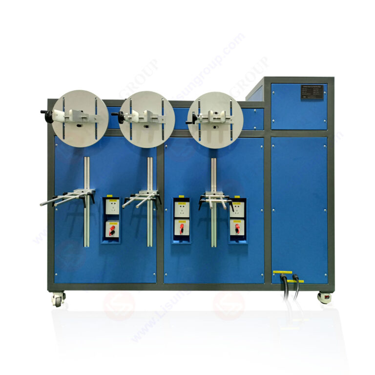
The LISUN SW Series offers three base configurations to match production throughput requirements. The SW-1 single-station unit suits R&D laboratories conducting sequential material evaluations. The SW-2 dual-station model enables side-by-side comparison of two cord types under identical conditions. The SW-6 six-station configuration supports high-throughput production quality assurance, testing six specimens simultaneously. All models share identical PLC control architecture and servo drive systems, ensuring test result consistency across stations. The following table provides detailed technical comparison:
| Parameter | SW-1 Single Station | SW-2 Dual Station | SW-6 Six Station | IEC 60884-1 Minimum Requirement |
|---|---|---|---|---|
| Test Stations | 1 | 2 | 6 | 1 (minimum) |
| Bending Angle Range | 0° – 180° | 0° – 180° | 0° – 180° | 90° ± 1° |
| Bending Frequency | 10 – 60 cycles/min | 10 – 60 cycles/min | 10 – 60 cycles/min | 60 cycles/min |
| Max Cycle Count | 999,999 | 999,999 | 999,999 | 10,000 (typical) |
| Load Current Range | 0.1 – 25 A | 0.1 – 25 A | 0.1 – 25 A | 1.25 × rated current |
| Cord Diameter Capacity | 6 – 18 mm | 6 – 18 mm | 6 – 18 mm | Per cord specification |
| Power Supply | AC 220V 50/60Hz | AC 220V 50/60Hz | AC 380V 50/60Hz | N/A |
| Weight | 45 kg | 62 kg | 98 kg | N/A |
3.2 Parameter Adjustability and User Interface
All SW Series models feature a 7-inch color touchscreen HMI for parameter entry and real-time monitoring. Operators can set bending angle, frequency, cycle count, load current threshold, and failure detection sensitivity without programming knowledge. The PLC stores up to 50 test protocols for rapid recall. Real-time displays show current cycle count, instantaneous current, elapsed test time, and station status. Each station includes individual start/stop controls, allowing independent operation even during multi-station testing. The interface supports password-protected parameter lock to prevent unauthorized modifications—critical for accredited laboratory environments.
3.3 Data Logging and Export Capabilities
The integrated data acquisition system records complete test histories, including cycle count at failure, failure mode (open circuit, short circuit, intermittent), test duration, and parameter set. Logged data is exportable via USB port in CSV format for statistical process control (SPC) analysis. The system can generate Weibull distribution plots for mean cycles to failure (MCTF) calculations, enabling engineers to estimate product reliability at warranty periods. For audit compliance, the system maintains a tamper-proof log of all parameter changes and test interruptions.
4.1 Household Appliance Manufacturing
For washing machines, refrigerators, and vacuum cleaners, the power cord bending test validates cord durability during normal use and storage. The SW Series simulates the flexing stress encountered when appliances are moved or when cords are wrapped around storage hooks. Engineers can program test profiles that replicate real-world usage patterns—for example, 90° bends at 30 cycles per minute for 20,000 cycles, followed by 180° bends at 15 cycles per minute for 5,000 cycles. Failures detected at early cycle counts prompt design changes in cord material, conductor strand count, or jacket thickness. One appliance manufacturer reduced field failure rates by 73% after implementing the SW-6 for production lot validation.
4.2 Hand-Held Electric Tool Production
Power tool cords experience extreme flexing near the tool body during operation. The SW Series, with its adjustable pendulum mass, can simulate the additional load from the tool’s weight during bending. Typical test protocols for circular saws require 15,000 cycles at 90° with 8 A load current; for drills, 10,000 cycles at 60° with 5 A load current. The SW-2 dual-station configuration allows simultaneous testing of two tool models, accelerating design validation cycles. Data from bending tests directly informs cord selection: cords with >1% strand breakage below 8,000 cycles are rejected, while those surviving 12,000+ cycles are approved for production.
4.3 Plug/Socket Component Supplier Qualification
Component suppliers must demonstrate that cord anchors and strain relief bushings maintain mechanical integrity under bending stress. The SW Series tests the complete cord assembly, including molded plugs, strain reliefs, and cable entries. Testing to IEC 60884-1 Clause 23.3 requires 5,000 cycles for cord anchors—a 50% reduction from full cord tests—but with a more stringent failure criterion of no cord displacement at the anchor point. The current-based detection system identifies conductor breakage at the anchor junction, while visual inspection after testing verifies anchor displacement. Suppliers using the SW-6 can qualify 60 cord assemblies per 8-hour shift (assuming 1,000-cycle tests), dramatically improving throughput.
4.4 Third-Party Compliance Testing Laboratories
Accredited testing laboratories require equipment with traceable calibration and repeatable results. The SW Series offers NIST-traceable calibration certificates for timing circuits, current sensors, and angle encoders. Labs can configure the system to run fully automated test sequences overnight, with automatic shutdown upon completion or failure. The data export feature generates test reports in formats accepted by IECEE CB Scheme and UL certification bodies. Multi-station configurations enable labs to process multiple client samples simultaneously, reducing turnaround time while maintaining ISO/IEC 17025 traceability requirements.
5.1 Site Preparation and Electrical Requirements
The SW Series requires a stable, vibration-free surface with load capacity exceeding the unit weight plus test specimen loads. For SW-6 models, a reinforced concrete floor is recommended. Electrical supply must meet local codes: SW-1 and SW-2 operate on AC 220V 50/60 Hz (10 A circuit), while SW-6 requires AC 380V 50/60 Hz (16 A three-phase circuit). Grounding resistance must be below 4 Ω to ensure operator safety and prevent measurement interference from electromagnetic noise. Ambient temperature should be maintained at 23°C ± 5°C. Relative humidity below 80% non-condensing prevents moisture accumulation on electronic components.
5.2 Calibration Procedures and Frequency
Annual calibration is recommended for maintaining measurement accuracy. The bending angle verification uses a digital protractor with ±0.1° resolution, mounted on the pendulum arm. Load current calibration employs a precision shunt resistor and calibrated multimeter (0.1% accuracy). Cycle counting is verified against an external counter. The PLC self-diagnostics include angle encoder linearity checks, servo motor torque limit verification, and current sensor offset correction. Calibration certificates should document all measurement uncertainties per ISO/IEC 17025 guidelines. Between calibrations, daily verification using a known reference cord (with documented MCTF) ensures system stability.
5.3 Routine Maintenance and Troubleshooting
Weekly maintenance includes cleaning of guide rails and linear bearings, inspection of pendulum pivot points for wear, and verification of clamp jaw alignment. Monthly tasks involve lubrication of servo motor bearings (per manufacturer specifications), checking torque on all fasteners, and cleaning air intake filters on the control cabinet. Quarterly maintenance replaces the backup battery in the PLC (typical lifespan: 5 years) and inspects all electrical connections for corrosion. Common troubleshooting issues include: current sensor drift (zero-offset adjustment required), servo motor overheating (check ventilation), and angle encoder misalignment (re-zero procedure via HMI). The user manual provides fault codes and corrective actions for 30+ diagnostic messages.
6.1 Precision and Repeatability Enhancements
Conventional mechanical bending testers use cam-driven mechanisms with fixed oscillation profiles, limiting adjustability to physical part replacement. The SW Series’ PLC-servo architecture enables software-defined parameter changes without mechanical modifications. Repeatability measured across 50 consecutive tests on the same cord type yields cycle count standard deviation below 2%, compared to 8-12% for cam-driven systems. This precision reduces the required sample size for statistically significant results—five specimens instead of fifteen—saving material costs and testing time. The servo drive maintains constant angular velocity regardless of cord stiffness variations, eliminating a common source of error in mechanical systems.
6.2 Multi-Station Parallel Testing Efficiency
The SW-6 six-station configuration provides six independent test channels, each with its own load circuit and failure detection. Conventional systems require separate testers for each specimen, occupying six times the floor space and requiring six operator interventions. With the SW-6, a single operator can start all six tests simultaneously. The system automatically compensates for minor differences in cord stiffness between stations, ensuring identical bending angles via individual servo motor calibration. For a typical 10,000-cycle test at 60 cycles per minute (2.78 hours per test), the SW-6 completes six tests in the same time a single-station system requires for one—a 500% throughput improvement.
6.3 Automated Failure Analysis and Reporting
The current-based detection system not only stops the test upon failure but also classifies the failure type: open circuit (immediate current drop to zero), short circuit (current surge above 150% of setpoint), or intermittent (momentary current fluctuation >50% of setpoint for >10 ms). This classification enables rapid root cause analysis. For example, intermittent failures often indicate partial strand breakage or connector fretting, while open circuits suggest complete conductor separation. The system generates a Pareto chart of failure modes after each test batch, guiding design improvement priorities. Reports are automatically formatted for inclusion in certification documentation packages.
7.1 Statistical Process Control (SPC) Integration
The SW Series’ data export capability supports real-time SPC monitoring. Engineers can import CSV files into statistical software to generate X-bar and R charts for cycle count data. Control limits calculated from initial qualification tests (e.g., MCTF = 12,500 cycles, ±500 cycles) flag production batches exceeding warning limits. When a batch’s MCTF falls below 10,000 cycles, the quality system automatically initiates a non-conformance report (NCR) and suspends cord usage until root cause investigation completes. This closed-loop quality control has reduced supplier cord rejections by 65% in one appliance manufacturer’s supply chain.
7.2 Traceability and Audit Trail Compliance
The PLC maintains a digital log of all parameter changes, test starts/stops, and diagnostic events, each timestamped and attributed to operator login credentials. This audit trail satisfies ISO 9001:2015 Clause 7.5.3 requirements for document control and ISO 17025 Clause 5.8 for corrective action tracking. In the event of a field failure, the traceability system can retrieve the exact test parameters and results for the specific cord lot, enabling correlation analysis between test results and field performance. The system supports 21 CFR Part 11 compliance for pharmaceutical equipment manufacturers requiring electronic signature validation.
7.3 Remote Monitoring and Multi-Site Consistency
Optional network connectivity enables remote monitoring via Ethernet or Wi-Fi. Quality managers can view real-time test status, download completed test data, and receive email alerts on test completions or failures from multiple tester locations. This capability ensures consistent test execution across geographically dispersed manufacturing sites. Centralized parameter updates prevent site-to-site variation—for example, ensuring all sites test to the same bending angle tolerance. For global companies, this harmonization supports unified product quality standards across regional production facilities.
The Industrial PLC-Controlled Power Cord Bending Tester, represented by the LISUN SW Series, delivers precise, automated, and standards-compliant validation of power cord flexibility endurance. Its PLC-servo architecture provides programmability, repeatability, and multi-station scalability unmatched by conventional mechanical testers. Compliance with IEC 60884-1, IEC 60745-1, IEC 60335-1, and GB/T 2099.1 ensures global regulatory acceptance, while current-based failure detection enables objective failure classification and data-driven quality improvements. For R&D engineers, the system accelerates material qualification through customizable test profiles and 50% reduction in specimen requirements. For production quality control, the SW-6’s six-station configuration delivers 500% throughput improvement over single-station alternatives. Third-party laboratories benefit from automated report generation and traceability systems that simplify accreditation processes. By integrating with statistical process control and quality management systems, the SW Series transforms cord reliability testing from a regulatory compliance activity into a strategic quality optimization tool. Engineers and managers seeking to reduce field failure rates, streamline certification workflows, and enhance product durability will find this power cord bending tester an indispensable asset in their testing infrastructure.
Q1: What is the minimum and maximum cord diameter that the SW Series bending tester can accommodate?
A: The SW Series accommodates cord diameters from 6 mm to 18 mm across all models (SW-1, SW-2, SW-6). The clamping mechanism uses interchangeable jaw inserts to grip cords without crushing or deforming the outer jacket. For cords below 6 mm diameter, optional reducing sleeves are available. For cords above 18 mm, custom mandrels and clamp jaws can be fabricated to order. The standard bending radii range from 10 mm to 50 mm, adjustable via mandrel selection. IEC 60884-1 does not mandate a specific diameter range, but the 6-18 mm range covers >95% of household appliance and power tool cords. When testing cords near the maximum diameter, ensure the bending angle verification accounts for increased stiffness, which may require recalibration of the servo motor torque limits.
Q2: How does the current-based failure detection system distinguish between conductor breakage and intermittent connection?
A: The system uses three detection criteria: open circuit detection triggers when load current drops below 10% of the setpoint for more than 200 ms, indicating complete conductor separation. Short circuit detection activates when current exceeds 150% of setpoint for more than 100 ms. Intermittent connection detection monitors current fluctuations exceeding 50% of setpoint for durations between 10 ms and 200 ms. The PLC records the specific failure mode for each event, along with the exact cycle count. This granularity allows engineers to identify partial strand breakage (intermittent mode) versus complete conductor failure (open circuit mode). In compliance with IEC 60884-1 Clause 23.2, the system also records the number of intermittent events before final failure, providing data for fatigue life analysis.
Q3: Can the SW Series bending tester be integrated with an environmental chamber for temperature or humidity controlled testing?
A: Yes, the SW Series can be integrated with environmental chambers for testing under controlled temperature and humidity conditions. The bending mechanism is designed with sealed bearings and corrosion-resistant materials suitable for temperatures from -10°C to +60°C and humidity up to 95% non-condensing. The control cabinet must be placed outside the environmental chamber to prevent electronic component damage. A pass-through port with sealed gland accommodates the cord connections. Testing at elevated temperatures (e.g., 60°C per IEC 60335-1 Clause 25.13) accelerates polymer degradation, providing accelerated life test data. For GB/T 2099.1 compliance, the 23°C ± 2°C requirement is easily maintained with a laboratory-grade temperature controller. Customers should specify environmental integration requirements at order to ensure proper sealing and cable lengths.
Q4: What is the typical calibration interval for the SW Series, and what parameters require verification?
A: LISUN recommends annual calibration for the SW Series, which aligns with ISO/IEC 17025 requirements for accredited laboratories. The calibration procedure verifies four key parameters: bending angle accuracy (±0.5° tolerance), bending frequency (±1 cycle/min tolerance), load current measurement (±2% of reading), and cycle counting accuracy (±0.1% of total count). Verification tools include a digital protractor (accuracy ±0.1°), a tachometer (accuracy ±0.5 rpm), a precision shunt resistor and calibrated multimeter (accuracy ±0.1%), and an external cycle counter. The calibration certificate must document measurement uncertainties per ISO Guide 98-3 (GUM). Daily operator verification can use a reference cord with known MCTF—if the test completes within ±10% of the documented MCTF, the system is operating correctly. The PLC logs all calibration adjustments with date/time stamps for full traceability.
Q5: How does the multi-station SW-6 handle independently failed stations without affecting other ongoing tests?
A: Each of the six test stations on the SW-6 operates independently, with its own servo motor, current sensor, and failure detection logic. When a station detects a failure (open circuit, short circuit, or intermittent), it immediately stops its bending cycle and logs the failure data. The remaining five stations continue their test protocols without interruption. The PLC displays the status of each station individually on the HMI, showing cycle count, current status, and elapsed time. This independence is critical for production testing, where cord samples may have varying durability. For example, if one cord fails at 3,000 cycles, the other five continue to 10,000 cycles, providing both early failure data and survival analysis data from the same test batch. The individual station controls also allow operators to start and stop stations independently for loading/unloading without affecting active tests.