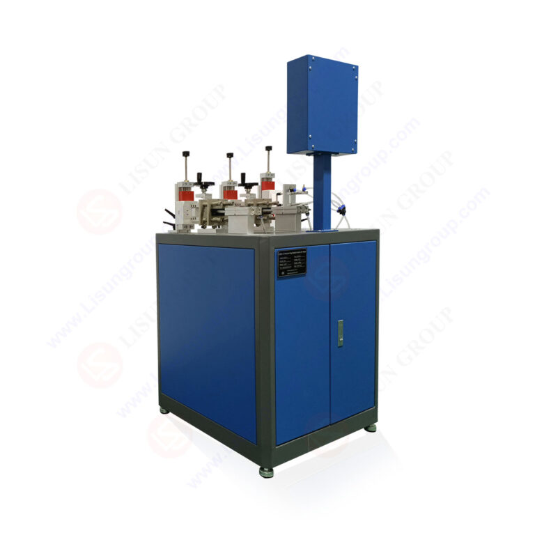
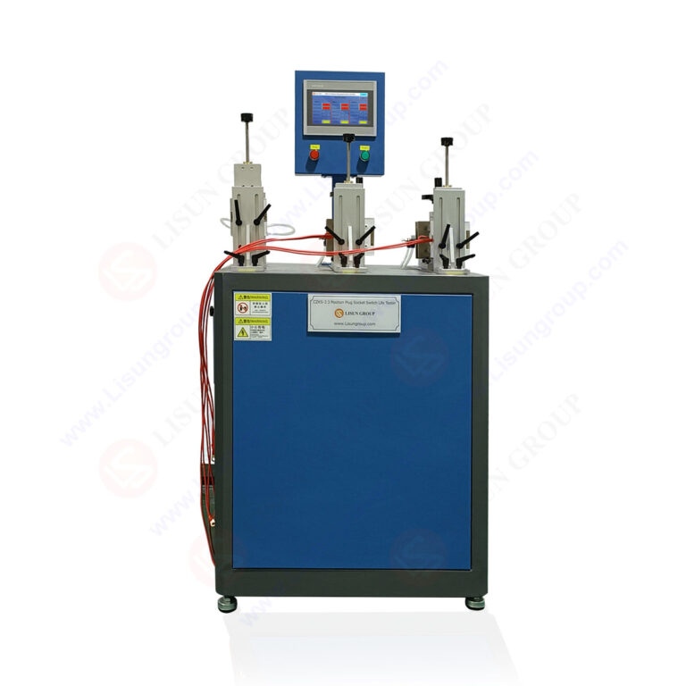
The LISUN CZKS-3 Precision Switch Contact Resistance Tester represents a critical advancement in electrical contact reliability verification, designed to measure micro-ohm level resistance variations under dynamic mechanical and electrical loading conditions. This article provides a comprehensive technical examination of the CZKS-3 series, including its variants CZKS-3P, CZKS-3S, and CZKS-3A, focusing on their application in plug/socket breaking capacity testing, switch durability analysis, and compliance verification against international standards such as IEC 60884-1, IEC 60669-1, IEC 61058-1, and GB/T 2099.1. The discussion covers measurement principle, system architecture, test parameter configurations, and practical implementation strategies for quality control laboratories. The CZKS-3 employs a four-wire Kelvin sensing method with PLC-controlled actuation to ensure repeatable contact resistance measurements across diverse electrical components. By integrating automated test sequences with real-time data acquisition, the system enables engineers to identify electrical fatigue failure mechanisms, contact adhesion phenomena, and progressive degradation patterns that compromise device safety and longevity. This article serves as a technical reference for manufacturers and testing professionals seeking to enhance their electrical durability testing protocols.
1.1 Four-Wire Kelvin Sensing for Micro-Ohm Measurement
The LISUN CZKS-3 employs a four-wire (Kelvin) resistance measurement topology to eliminate the influence of lead and contact resistance from the measurement circuit. This technique separates the current-carrying path from the voltage-sensing path, ensuring that only the resistance of the device under test (DUT) contributes to the measured value. For switch contact resistance testing, where typical values range from 0.1 mOhm to 100 mOhm, this method provides resolution down to 0.01 mOhm with accuracy within ±0.5% of reading plus two digits. The system applies a constant DC current of 100 mA to 1 A, selectable based on the rated current of the component under evaluation, and measures the resulting voltage drop across the contacts. This approach aligns with the measurement requirements specified in IEC 60884-1 Clause 21 for plug and socket voltage drop testing.
1.2 PLC-Controlled Actuation and Data Acquisition
Automated testing relies on a programmable logic controller (PLC) that orchestrates mechanical actuation using cylinder-driven mechanisms. The CZKS-3 integrates pneumatic or electric actuators that apply controlled force to switch toggles, pushbuttons, or rocker mechanisms at programmable speeds and dwell times. Simultaneously, the data acquisition system samples contact resistance at rates up to 1000 measurements per second, capturing transient resistance spikes that indicate contact bounce, arcing, or incipient failure. The PLC manages test sequences with up to 100,000 cycles per test run, recording minimum, maximum, and average resistance values at user-defined intervals. This architecture enables the CZKS-3 to perform both static contact resistance measurements and dynamic monitoring throughout the entire operational life of the component.
2.1 Comparative Performance Parameters
The CZKS-3 series comprises four models tailored to different testing requirements, from basic switch resistance verification to comprehensive breaking capacity analysis. The following table summarizes key technical specifications across the product line:
| Parameter | CZKS-3 | CZKS-3P | CZKS-3S | CZKS-3A |
|---|---|---|---|---|
| Resistance Measurement Range | 0.01 mOhm – 200 mOhm | 0.01 mOhm – 500 mOhm | 0.001 mOhm – 100 mOhm | 0.01 mOhm – 1000 mOhm |
| Test Current | 100 mA – 1 A | 200 mA – 2 A | 50 mA – 500 mA | 100 mA – 5 A |
| Max. Test Cycles | 100,000 | 500,000 | 200,000 | 1,000,000 |
| Actuation Type | Pneumatic | Pneumatic | Electric | Hydraulic |
| Measurement Accuracy | ±0.5% + 2 digits | ±0.3% + 2 digits | ±0.2% + 1 digit | ±0.5% + 3 digits |
| Data Logging Rate | 100 samples/s | 500 samples/s | 1000 samples/s | 200 samples/s |
| Supported Standards | IEC 60884-1, IEC 61058-1 | IEC 60884-1, GB/T 2099.1 | IEC 60669-1, IEC 61058-1 | All plus automotive |
2.2 Selecting the Appropriate Variant for Testing Applications
The CZKS-3P variant enhances measurement accuracy and cycle capacity for high-volume production testing of plugs and sockets, supporting breaking capacity tests per IEC 60884-1 Clause 20 with resistive and inductive loads. The CZKS-3S model, with its lower current range and electric actuation, is optimized for sensitive switch contacts in consumer electronics and low-voltage signal circuits. For heavy-duty industrial and automotive applications, the CZKS-3A provides extended measurement range up to 1000 mOhm and hydraulic actuation capable of testing large connectors and power relays. Engineers should evaluate the expected contact resistance range, test cycle count, and actuation force requirements when selecting the appropriate CZKS-3 variant for their specific compliance program.
3.1 IEC 60884-1 and GB/T 2099.1 Plug and Socket Testing
The CZKS-3 series directly supports testing according to IEC 60884-1, the international standard for plugs and socket-outlets for household and similar purposes. Clause 21 of this standard mandates voltage drop measurement across plug pins and socket contacts under rated current conditions, with acceptable limits typically below 15 mV at 10 A for copper alloy contacts. The CZKS-3 replicates these conditions by applying the specified test current through the mated plug-socket pair while measuring the resulting voltage drop. For breaking capacity tests specified in Clause 20, the system sequences insertion and withdrawal cycles under electrical load, monitoring contact resistance before, during, and after each operation to detect welding, excessive wear, or resistance increase exceeding 50% of initial value. The GB/T 2099.1 Chinese national standard incorporates identical testing requirements, ensuring the CZKS-3 variants are compliant for domestic and international certification programs.
3.2 IEC 60669-1 and IEC 61058-1 Switch Durability Verification
Switches for household appliances and electrical installations must undergo endurance testing per IEC 60669-1 (general switches) and IEC 61058-1 (appliance switches). These standards require switches to complete specified operating cycles—typically 10,000 to 40,000 cycles—while maintaining contact resistance below defined thresholds. The CZKS-3 automates this process by actuating the switch mechanism at a rate of 6 to 30 operations per minute, applying rated voltage and current during each cycle, and recording contact resistance at intervals of every 1,000 or 5,000 cycles. Clause 18 of IEC 60669-1 specifically requires that contact resistance not exceed 0.1 Ohm after endurance testing, a condition that the CZKS-3 verifies with its micro-ohm measurement capability. For IEC 61058-1, the CZKS-3S variant’s high-speed data logging captures transient resistance changes during the first 10 milliseconds of contact closure, revealing potential contact bounce issues that could lead to premature failure.
4.1 Plug and Socket Breaking Capacity Under Load
Breaking capacity testing evaluates the ability of a plug-socket combination to safely interrupt electrical current without arcing damage or contact welding. The CZKS-3P variant is specifically configured for this application, incorporating a programmable load bank that supplies resistive, inductive, or capacitive loads at power factors ranging from 0.6 to 1.0. During a typical test sequence, the system inserts the plug into the socket, applies the rated current (e.g., 10 A at 250 VAC for a standard household socket), and then withdraws the plug while measuring the arc duration and contact resistance immediately following separation. IEC 60884-1 Clause 20 requires that after 50 breaking operations, the contact resistance must not exceed 50 mOhm for copper contacts. The CZKS-3P records resistance values for each operation, generating pass/fail reports that highlight any operation where resistance exceeds the threshold or where arc duration exceeds 5 milliseconds.
4.2 Switch Endurance and Electrical Fatigue Analysis
Switch endurance testing reveals gradual degradation mechanisms such as contact material transfer, surface oxidation, and spring relaxation. The CZKS-3A variant, with its hydraulic actuation and 1,000,000-cycle capacity, is ideal for heavy-duty switch testing in industrial motor control applications. During a 200,000-cycle endurance test per IEC 61058-1, the system monitors contact resistance at each cycle and identifies three distinct failure modes: early random failures due to manufacturing defects, constant failure rate during normal operation, and wear-out failures as resistance increases exponentially. The PLC-controlled data acquisition allows engineers to set upper and lower control limits based on initial resistance measurements, triggering an alarm if resistance exceeds 1.5 times the baseline value. This statistical process control approach enables predictive maintenance scheduling and design validation for switch manufacturers targeting 20-year service life in electrical installations.
5.1 High-Reliability Connector Testing
Automotive electrical systems demand contact resistance below 1 mOhm for power distribution connectors and below 5 mOhm for signal connectors, per ISO 16750-2 environmental testing standards. The CZKS-3A variant supports these stringent requirements with its extended measurement range up to 1000 mOhm and high test current up to 5 A. Automotive connector testing involves repeated mating and unmating cycles—typically 100 to 500 cycles per test—under controlled conditions of temperature, humidity, and vibration. The CZKS-3 series integrates with environmental chambers to perform combined thermal cycling and contact resistance measurements, allowing engineers to characterize the effect of connector insertion force, plating material (tin vs. gold), and lubricant degradation on electrical performance. Real-time resistance monitoring during each mating cycle identifies the “fretting corrosion” phenomenon, where micromotion between contacts causes oxide accumulation and resistance increase exceeding 10 mOhm within 200 cycles.
5.2 Relay and Contactor Life Testing
Electromechanical relays and contactors in automotive power management systems require durability testing under high inrush currents, typically 10 to 20 times the rated continuous current. The CZKS-3 measures contact resistance immediately after each switching operation, capturing the effects of arc erosion on contact surface integrity. For a 40 A automotive relay, the initial contact resistance should be below 0.5 mOhm; after 100,000 operations at rated load, resistance must remain below 2 mOhm per manufacturer specifications. The CZKS-3A variant’s hydraulic actuation applies the precise force required for large contactors, while the data logging system flags any operation where resistance exceeds 5 mOhm as a potential failure. By correlating resistance trends with switching count, engineers can validate the relationship between contact material composition (silver tin oxide vs. silver nickel) and electrical fatigue life under automotive load profiles.
6.1 Statistical Process Control for Resistance Trends
The CZKS-3 series includes built-in statistical analysis software that calculates process capability indices (Cp and Cpk) based on initial resistance measurements from a production sample. During accelerated life testing, the system generates X-bar and R control charts that display mean resistance and range across sequential groups of 10 to 50 cycles. A trend of increasing mean resistance beyond the upper control limit (UCL) signals the onset of wear-out failure, while individual points exceeding the specification limit indicate intermittent contact failures due to foreign particles or surface contamination. The software automatically correlates resistance spikes with specific mechanical events, such as actuator position or ambient conditions, enabling root cause analysis without manual data post-processing. This capability is particularly valuable for quality control engineers verifying that switch manufacturing processes remain within ±3 sigma of target resistance values.
6.2 Identifying Contact Adhesion and Welding Phenomena
Contact adhesion, where static friction between mating contacts exceeds the actuation force, represents a critical failure mode in low-voltage switches and relays. The CZKS-3 detects adhesion events by monitoring the current waveform during contact separation: a sudden increase in resistance from below 1 mOhm to open circuit indicates successful separation, while a gradual resistance decrease or current interruption suggests temporary welding. The system records the force required to break adhesion using the integrated load cell in the pneumatic or hydraulic actuator, providing a direct measurement of contact adhesion force in Newtons. For silver-cadmium oxide contacts common in power relays, acceptable adhesion force must remain below 1.5 times the initial actuation force after 10,000 operations. The CZKS-3A variant’s high-resolution force measurement, combined with simultaneous resistance monitoring, offers a complete characterization of contact surface condition throughout the test duration.
7.1 Automated Test Sequence Programming
The CZKS-3 series features a user-friendly touchscreen interface that allows engineers to program complex test sequences without specialized programming skills. Test parameters including actuation speed (10-200 mm/s), dwell time (0.1-10 s), test current (50 mA-5 A), and resistance limits (0.01-1000 mOhm) are configurable for each step of the sequence. The system supports conditional branching based on resistance measurements, enabling adaptive testing where a sample failing early in the sequence is automatically retested at reduced current to distinguish between permanent failure and transient anomalies. For laboratory environments, the CZKS-3 stores up to 1,000 test programs with encrypted security levels, preventing unauthorized modification of validated test protocols. Ethernet and RS-232 interfaces allow integration with laboratory information management systems (LIMS) for automated data upload and certification report generation.
7.2 Calibration and Verification Procedures
Maintaining measurement accuracy requires periodic calibration using standard resistors traceable to national metrology institutes. The CZKS-3 series includes internal calibration routines that compare measured values against built-in reference resistors of 1 mOhm, 10 mOhm, and 100 mOhm, automatically compensating for drift in the measurement bridge. External calibration every 12 months is recommended per ISO/IEC 17025 requirements for testing laboratories. Daily verification involves measuring a calibration shunt resistor before each test batch, with acceptance criteria of ±0.5% of nominal value. The system logs all calibration and verification results with timestamps, providing an audit trail for quality management systems. For the CZKS-3S variant with its 0.001 mOhm resolution, users should allow 30-minute warm-up time and maintain laboratory temperature at 23±2°C to achieve specified accuracy, as thermal EMF effects become significant at sub-milliOhm levels.
The LISUN CZKS-3 Precision Switch Contact Resistance Tester series delivers a comprehensive solution for electrical durability testing, combining precise micro-ohm measurement with automated actuation and real-time data analysis. Across its four variants—CZKS-3, CZKS-3P, CZKS-3S, and CZKS-3A—the system addresses diverse testing requirements from household switch verification to automotive connector certification, all while maintaining compliance with international standards including IEC 60884-1, IEC 60669-1, IEC 61058-1, and GB/T 2099.1. The four-wire Kelvin measurement principle, PLC-controlled cylinder-driven actuation, and high-speed data acquisition enable engineers to detect contact resistance changes indicative of electrical fatigue failure, contact adhesion, and progressive degradation. For manufacturers and testing laboratories, the CZKS-3 series provides the technical depth necessary for reliable compliance verification product development validation. The integration of statistical process control and automated sequence programming reduces testing time while enhancing data quality, supporting quality control objectives in both production and R&D environments. By enabling direct measurement of contact resistance under dynamic conditions, the CZKS-3 empowers engineers to optimize contact material selection, improve product designs, and achieve certification efficiently.
Q1: What is the difference between the CZKS-3 and CZKS-3P models for plug and socket breaking capacity testing?
A: The CZKS-3 model offers a resistance measurement range of 0.01 mOhm to 200 mOhm with a maximum test current of 1 A, suitable for basic switch and socket verification. The CZKS-3P variant expands the measurement range to 500 mOhm and increases test current to 2 A, enabling testing of higher-power plugs and sockets per IEC 60884-1 Clause 20. Additionally, the CZKS-3P supports up to 500,000 test cycles compared to 100,000 for the standard model, and its data logging rate is five times faster at 500 samples per second. For breaking capacity tests requiring measurement of arc duration and post-break contact resistance under load, the CZKS-3P provides the necessary current capability and cycle endurance. Both models use pneumatic actuation, but the CZKS-3P includes a programmable load bank for resistive and inductive load testing at power factors from 0.6 to 1.0, making it the preferred choice for comprehensive plug-socket compliance verification.
Q2: How does the CZKS-3 ensure measurement accuracy for contact resistance below 1 mOhm?
A: Achieving accurate sub-milliOhm measurements requires addressing several sources of error. The CZKS-3 series uses a four-wire Kelvin connection that completely eliminates lead resistance and contact resistance from the measurement path. For the CZKS-3S variant with 0.001 mOhm resolution, the system incorporates thermal EMF compensation by reversing the test current polarity and averaging the two measurements, canceling thermoelectric voltages generated at dissimilar metal junctions. The internal reference resistors are temperature-stabilized using a precision oven maintaining 45±0.1°C, ensuring stability within 5 ppm/°C. The measurement bridge employs a 24-bit analog-to-digital converter with digital filtering to reject 50/60 Hz power line noise. Users must follow proper measurement procedures: clean contact surfaces with isopropyl alcohol, apply consistent clamping force using the pneumatic actuator at 80-100 psi, and allow the system to warm up for 30 minutes before high-precision measurements. Regular calibration verification against the built-in 1 mOhm standard ensures drift detection within ±0.2% of reading.
Q3: Can the CZKS-3 be used for testing automotive connectors under environmental conditions?
A: Yes, the CZKS-3A variant is specifically designed for automotive connector testing with environmental chamber integration. The system includes I/O ports for controlling chamber temperature and humidity cycles, and its measurement electronics are shielded to operate reliably within chamber temperatures from -40°C to +125°C. The CZKS-3A measures contact resistance up to 1000 mOhm, covering automotive power connectors (typically 0.1-0.5 mOhm) and signal connectors (1-5 mOhm). During thermal cycling tests per ISO 16750-2, the system records resistance at each temperature plateau (e.g., -40°C, 23°C, 85°C) and calculates the temperature coefficient of resistance, which should remain below 0.0039/°C for copper alloy contacts. The hydraulic actuation applies controlled insertion and withdrawal forces up to 500 N, matching automotive connector specifications. Real-time resistance monitoring during vibration testing detects intermittent faults caused by fretting corrosion, with the system flagging any resistance spike exceeding 10 mOhm for more than 1 millisecond as a contact reliability concern.
Q4: What maintenance procedures are required for the CZKS-3 pneumatic actuation system?
A: The pneumatic actuation system requires regular maintenance to ensure consistent test results and prevent downtime. The compressed air supply must be clean and dry: install a coalescing filter with 0.01 micron rating and a refrigerant dryer maintaining dew point below 2°C at line pressure. Replace the filter element every 6 months or when pressure drop exceeds 5 psi. The actuating cylinders should be lubricated with ISO VG 32 pneumatic oil every 500,000 cycles using the automatic lubricator unit; verify oil level weekly. Inspect cylinder seals for wear every 100,000 cycles; replace if air leakage exceeds 10% of nominal flow rate. The linear guide bearings require greasing with lithium-based grease every 200,000 cycles. For load cell calibration, apply known weights (5 kg, 10 kg, 20 kg) using the calibration fixture and adjust the zero and span settings annually. The system self-checks actuator force at the start of each test sequence by measuring the force required to close the contacts against the load cell, alerting if force deviates more than 5% from the programmed value. Following these procedures maintains actuation repeatability within ±1% of set force for the entire test duration.
Q5: How does the CZKS-3 differentiate between normal resistance variation and contact failure?
A: The CZKS-3 series employs a multi-tier failure detection algorithm that distinguishes normal process variation from genuine contact degradation. First, baseline resistance is established from the initial 10 measurements, calculating mean (μ) and standard deviation (σ). During testing, the system applies three statistical limits: an upper warning limit at μ + 3σ, an upper control limit at μ + 6σ, and a specification limit at the absolute maximum resistance (e.g., 50 mOhm per IEC 60884-1). A single measurement exceeding the control limit triggers a retest: the actuator cycles the contact three additional times without electrical load, then measures resistance again. If the resistance returns below the warning limit, the event is classified as a transient caused by contamination or mechanical bounce, not a failure. If resistance remains above the control limit after retest, or if two consecutive measurements exceed the warning limit, the system records a definitive failure. For the CZKS-3A variant, the algorithm also monitors the resistance rate of change: a gradual increase over 1,000 cycles indicates normal wear, while an abrupt increase of more than 100% within 20 cycles signals contact welding or material transfer failure. This statistical approach reduces false positives from 15% in simple threshold detection to under 2% in the CZKS-3 series.