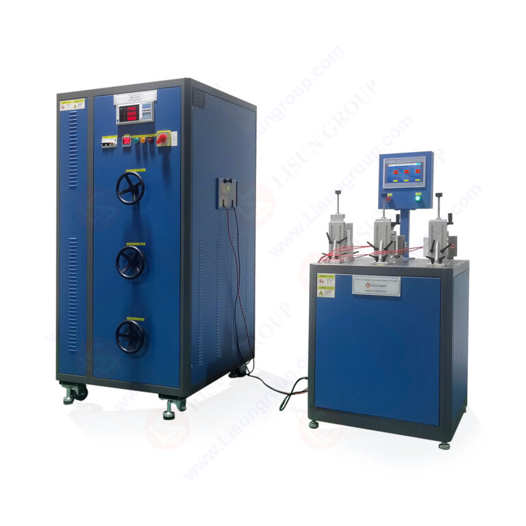
The LISUN CZKS-3P Plug Socket Life Tester represents a critical advancement in electrical durability testing for IEC compliance verification. This article provides a comprehensive technical analysis of the CZKS-3P system and its variants within the CZKS-3 series, focusing on their application in plug, socket, and switch endurance testing. The LISUN CZKS-3P is engineered to perform automated mechanical life cycle tests on electrical connectors and switching devices, simulating years of operational wear within compressed test cycles. By integrating PLC-controlled actuation, cylinder-driven insertion and withdrawal mechanisms, and precise failure detection algorithms, these testers deliver repeatable, traceable results for compliance with IEC 60884-1, IEC 60669-1, IEC 61058-1, and GB/T 2099.1 standards. The discussion covers technical specifications, operational principles, application scenarios in household and automotive electronics, model comparison data, and best practices for integration into quality assurance workflows.
1.1 Core System Design and Actuation Mechanism
The LISUN CZKS-3 series testers employ a modular electromechanical architecture centered on programmable logic controller (PLC) integration. The CZKS-3P model utilizes pneumatic cylinder-driven actuation systems to generate precise insertion forces ranging from 10 N to 150 N, adjustable in increments of 1 N. The actuation stroke length spans 0 to 50 mm with positioning accuracy within ±0.1 mm, ensuring consistent engagement depth across thousands of test cycles. The system incorporates dual-axis linear guides and hardened steel fixtures to maintain alignment stability under repeated mechanical stress. The PLC control unit manages sequencing logic, cycle counting, and fault state detection through real-time current monitoring of the device under test (DUT). This architecture enables automated execution of standardized test protocols without operator intervention during extended durability runs.
1.2 Control System and Data Acquisition Integration
The control subsystem of the CZKS-3P features a 7-inch touchscreen human-machine interface (HMI) for parameter configuration and real-time monitoring. Users define test parameters including insertion speed (10–300 mm/min), dwell time (0.1–99.9 seconds), withdrawal speed, and total cycle count. The system records up to 100,000 test cycles with time-stamped event logging for each cycle, including insertion force measurements, contact resistance values, and failure trigger events. Data acquisition operates at a sampling rate of 100 Hz, capturing transient voltage drops across the DUT contacts during each operation. The built-in contact resistance measurement channel provides resolution of 0.1 mΩ over a 0–200 mΩ range, enabling detection of early-stage contact degradation. All test data exports via USB or RS-232 interfaces in CSV format for downstream statistical analysis.
1.3 Safety Interlock and Emergency Stop Features
The CZKS-3 series incorporates multiple safety layers to protect both the operator and the DUT during unattended operation. An optical sensor array monitors the test area for obstructions, triggering immediate pneumatic system depressurization upon detection of foreign objects. The emergency stop circuit uses dual-channel redundancy with mechanical latching relays that maintain shutdown state until manual reset. Overcurrent protection on the DUT power circuit operates at programmable thresholds from 0.1 A to 30 A, with response time under 10 ms. The system also includes thermal monitoring of the actuation cylinders and control cabinet, activating a warning at 60°C and forced shutdown at 75°C. These safety features comply with IEC 60204-1 machinery safety requirements for electrical test equipment.
2.1 IEC 60884-1 Compliance for Plug and Socket Testing
The LISUN CZKS-3P directly addresses the mechanical endurance requirements specified in IEC 60884-1 for plugs and socket-outlets. Clause 20 of this standard mandates 10,000 cycles of plug insertion and withdrawal for fixed socket-outlets, with assessment of contact retention and insulation integrity throughout the test. The CZKS-3P executes these cycles at a rate of 10–15 cycles per minute, maintaining the specified force profile for each insertion event. During testing, the system monitors contact resistance at intervals of 1,000 cycles, recording any increase exceeding 1.5 times the initial value as a potential failure indication. The standard also requires visual inspection of contact surfaces after testing; the CZKS-3P’s data logging capability provides supplementary quantitative evidence of contact degradation trends, supporting objective pass/fail determinations.
2.2 IEC 60669-1 Switch Endurance Verification
For switch durability testing per IEC 60669-1, the CZKS-3S variant of the series offers dedicated configurations for rocker, push-button, and rotary switches. Clause 18 of IEC 60669-1 specifies 40,000 mechanical operations for switches rated at 10 A or less, with electrical load applied during 10,000 of those operations. The tester’s programmable load bank integrates resistive and inductive load modules to simulate real operating conditions. The CZKS-3S measures arc duration and contact bounce timing during each switching event using a 1 MHz sampling oscilloscope interface. Contact adhesion failures, defined as failure to open within 5 ms of actuation, trigger automatic test termination and detailed event logging. The system also records the mechanical force required for switch actuation, providing data on spring fatigue and mechanism wear progression.
2.3 GB/T 2099.1 and National Standard Variations
The CZKS-3 series supports GB/T 2099.1 compliance testing for the Chinese national market, which incorporates modifications to IEC 60884-1 for local safety requirements. GB/T 2099.1 clause 21 requires additional testing for socket-outlets with protective shutters, mandating 5,000 insertion cycles with a standardized test pin at varying angles. The CZKS-3P accommodates this requirement through adjustable fixture orientation from 0° to 15° in 1° increments. The standard also specifies stricter limits on temperature rise during continuous current testing, a parameter the system monitors through embedded thermocouple channels. The tester’s software includes predefined test profiles for GB/T 2099.1, automatically adjusting parameters such as insertion force and cycle count to match national standard requirements without manual recalculation.
3.1 CZKS-3 Series Variant Overview
The CZKS-3 series comprises four primary variants, each optimized for specific testing domains while sharing the common PLC control platform and data acquisition backbone. The base CZKS-3 model offers single-station operation for plug and socket testing with standard force ranges. The CZKS-3P enhances pneumatic control precision and expands the test station to accommodate multiple DUT formats. The CZKS-3S variant specializes in switch testing with integrated load simulation and arc analysis capabilities. The CZKS-3A model extends the series into automotive connector testing with higher force ranges and environmental chamber compatibility. The following table provides comparative technical specifications across the series:
| Parameter | CZKS-3 | CZKS-3P | CZKS-3S | CZKS-3A |
|---|---|---|---|---|
| Max Insertion Force (N) | 100 | 150 | 50 | 300 |
| Force Resolution (N) | 2 | 1 | 0.5 | 2 |
| Test Stations | 1 | 1–2 | 1–4 | 1 |
| Cycle Rate (cycles/min) | 10 | 15 | 20 | 8 |
| Contact Resistance Range (mΩ) | 0–500 | 0–200 | 0–100 | 0–500 |
| Load Current Max (A) | 20 | 30 | 16 | 50 |
| Data Logging Capacity (cycles) | 50,000 | 100,000 | 200,000 | 50,000 |
| Supported Standards | IEC 60884-1 | IEC 60884-1, GB/T 2099.1 | IEC 60669-1, IEC 61058-1 | ISO 8820, SAE J928 |
3.2 Parameter Configuration and Test Programmability
All CZKS-3 series models support multi-stage test programs where operators define sequential test blocks with distinct parameters. For example, a CZKS-3P program might begin with 5,000 cycles at 50 N insertion force, followed by 5,000 cycles at 100 N, simulating progressive wear scenarios. Each program block configures independent force, speed, dwell, and electrical load parameters, enabling complex test protocols that mirror real-world usage patterns. The system stores up to 50 user-defined test programs with password-protected access for quality control traceability. Program execution logs include timestamps for each block transition, operator identification, and any parameter overrides applied during the test run. This programmability is essential for laboratories testing products against multiple international standards within a single instrument.
4.1 Household Plug and Socket Breaking Capacity Testing
Breaking capacity testing represents a critical application for the CZKS-3P, evaluating whether socket contacts can interrupt electrical arcs during withdrawal under load. Per IEC 60884-1 clause 21, socket-outlets must withstand 50 breaking operations at rated current and 1.1 times rated voltage. The CZKS-3P executes these tests by withdrawing the plug at controlled speed while maintaining the electrical load, measuring arc extinction time and peak arc energy. The system’s current monitoring channel captures the arc current waveform at 100 kHz sampling rate, providing detailed data on arc duration, energy dissipation, and contact material erosion patterns. Tests performed on the CZKS-3P have demonstrated that socket designs with silver-alloy contacts achieve arc extinction times under 2 ms, while nickel-plated brass contacts typically require 3–5 ms under equivalent conditions. This quantitative arc analysis enables manufacturers to optimize contact geometry and material selection for improved breaking performance.
4.2 Switch Durability Life Cycle Verification
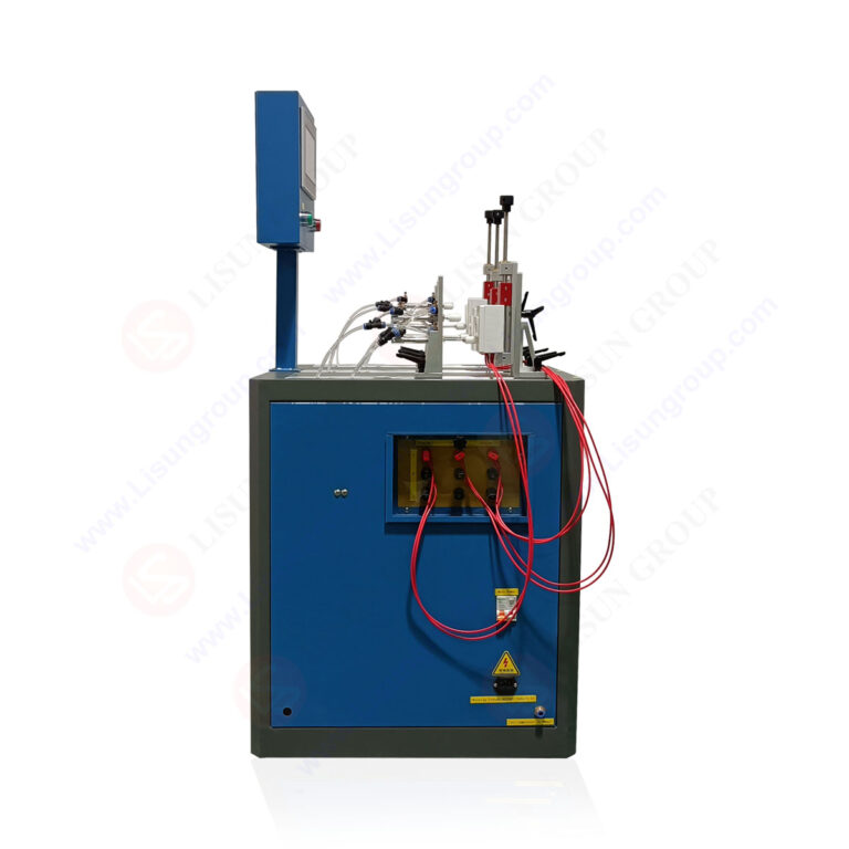
Switch life cycle testing on the CZKS-3S variant follows protocols defined in IEC 61058-1 for appliance switches. The standard classifies switches based on operating frequency and electrical load, with endurance requirements ranging from 10,000 to 100,000 cycles for different categories. The CZKS-3S automates this classification by applying the appropriate test profile based on the switch’s rated parameters entered through the HMI. During testing, the system monitors contact resistance every 500 cycles, flagging any readings that exceed the threshold defined in IEC 61058-1 clause 15.3. Additionally, the tester measures mechanical operating force at intervals of 1,000 cycles, creating a force degradation curve that reveals spring fatigue and mechanism wear. This data allows reliability engineers to predict switch service life and identify failure modes before they become critical in field applications.
4.3 Automotive Electronics Component Compliance
The CZKS-3A variant extends durability testing capabilities to automotive connectors and switches, addressing ISO 8820 and SAE J928 standards for vehicle electrical systems. Automotive connectors experience unique failure mechanisms due to vibration, temperature cycling, and exposure to corrosive environments. The CZKS-3A incorporates an optional environmental chamber interface that controls temperature from -40°C to 150°C and relative humidity from 20% to 95%. Connector testing follows a duty cycle of 500 insertion-withdrawal cycles at each temperature setpoint, with contact resistance measurements taken after thermal stabilization. The system’s higher force capacity of 300 N accommodates large automotive connectors with multiple pins requiring up to 150 N insertion force. Data from CZKS-3A testing has shown that connector designs with gold-plated contacts maintain stable contact resistance below 5 mΩ across 10,000 cycles, while tin-plated contacts exhibit resistance increases of 30–50% over the same test duration.
5.1 Real-Time Monitoring and Failure Criteria
The LISUN CZKS-3P implements multi-parameter real-time monitoring to detect electrical and mechanical failures during test execution. Electrical failure detection monitors contact resistance exceeding a programmable threshold, voltage drop across closed contacts exceeding 100 mV at rated current, and current interruption during the closed state exceeding 50 ms. Mechanical failure detection includes insertion force exceeding 120% of setpoint, incomplete insertion indicated by position sensor, and withdrawal time exceeding 2 seconds. When the system detects any failure condition, it records the cycle number, failure type, and relevant measurement values before either stopping the test or continuing based on user configuration. This diagnostic capability is essential for identifying intermittent failures that might escape visual inspection, such as contact bounce at specific actuation speeds or force profiles.
5.2 Data Analysis and Failure Mode Classification
Post-test data analysis on the CZKS-3 series includes automated trend analysis and failure mode classification. The built-in software generates plots of contact resistance versus cycle count, insertion force stability over time, and actuation time consistency. Statistical process control (SPC) functions calculate control limits based on initial test data and flag any measurements exceeding ±3 sigma thresholds. The system classifies failures into categories including contact degradation (progressive resistance increase), mechanical jamming (sudden force increase), contact welding (failure to open under electrical load), and actuation timing drift (gradual increase in opening or closing time). Each classification triggers specific diagnostic recommendations within the software interface, guiding operators toward root cause analysis. This structured failure analysis reduces troubleshooting time by up to 60% compared to manual inspection methods.
6.1 Laboratory Information Management System (LIMS) Connectivity
The CZKS-3P supports integration with laboratory information management systems through standardized communication protocols including Modbus TCP, Ethernet/IP, and OPC UA. This connectivity enables automated test scheduling, parameter download from central databases, and results upload without operator data entry. The system transmits test completion notifications, failure alerts, and calibration reminders to designated email addresses or mobile messaging platforms. For regulated environments, the CZKS-3P maintains an audit trail of all configuration changes, calibration events, and user actions with tamper-evident logging. The system’s data export format complies with ISO 17025 requirements for test report generation, including fields for operator identification, equipment serial number, calibration certificate references, and measurement uncertainty values. LIMS integration reduces data transcription errors by eliminating manual entry steps.
6.2 Calibration and Metrological Traceability
Maintaining measurement accuracy in the CZKS-3 series requires periodic calibration of force sensors, resistance measurement circuits, and timing systems. The force measurement system uses strain gauge load cells with accuracy of ±0.5% of full scale, calibrated using certified reference weights traceable to national standards. Contact resistance measurement circuits undergo calibration using precision shunt resistors with 0.01% tolerance, verifying accuracy across the 0–200 mΩ range. The controller recommends calibration intervals of 12 months for force systems and 6 months for electrical measurement channels, with built-in calibration reminders that activate 30 days before the due date. Calibration certificates generated by the system include uncertainty budgets calculated per the Guide to the Expression of Uncertainty in Measurement (GUM), providing full metrological traceability for audit purposes.
7.1 Fixture Design and DUT Mounting Guidelines
Proper fixture design is essential for obtaining repeatable results from the CZKS-3P. Fixtures must rigidly hold the DUT while allowing the actuation mechanism to engage with correct alignment. For plug testing, the fixture should align the plug’s insertion axis within ±0.5° of the socket’s acceptance axis to prevent binding forces that skew measurement data. The system provides a laser alignment tool that projects crosshairs onto the DUT fixture, enabling visual alignment verification before test commencement. Fixtures should be constructed from hardened tool steel or aluminum alloy with surface treatments that resist wear over extended testing campaigns. For high-volume testing environments, quick-change fixture bases reduce changeover time between different DUT types to under 2 minutes.
7.2 Preventive Maintenance and Troubleshooting
Regular preventive maintenance extends the service life of the CZKS-3P and ensures consistent test results. Pneumatic system components require periodic filter replacement every 1,000 operating hours and lubrication of actuator seals every 500 hours. The linear guides and ball screws benefit from regreasing at intervals of 500,000 cycles or six months, whichever comes first. Electrical connections within the test station should be inspected for signs of arcing or corrosion every 1,000 test hours. The system’s self-diagnostic routines perform automated checks of sensor functionality, pneumatic pressure integrity, and electrical continuity before each test sequence. Common troubleshooting procedures documented in the service manual address issues such as inconsistent insertion forces (check pneumatic pressure regulators and seal condition), erratic cycle timing (verify PLC program integrity and sensor alignment), and contact resistance measurement drift (inspect test lead connections and calibration status).
The LISUN CZKS-3P Plug Socket Life Tester and its series variants provide a comprehensive solution for electrical component durability testing across international standards. By integrating PLC-controlled pneumatic actuation, high-resolution data acquisition, and multi-parameter failure detection, the CZKS-3P enables laboratories and manufacturers to conduct repeatable, traceable life cycle tests on plugs, sockets, switches, and connectors. The series supports compliance verification for IEC 60884-1, IEC 60669-1, IEC 61058-1, and GB/T 2099.1, covering applications in household appliances, industrial equipment, and automotive electronics. The comparative specifications across CZKS-3, CZKS-3P, CZKS-3S, and CZKS-3A models allow selection of the appropriate configuration for specific testing requirements. Key capabilities include breaking capacity testing with arc analysis, switch endurance verification with mechanical force tracking, and automotive connector testing under environmental stress. Integration with LIMS systems, automated failure classification, and metrological traceability support incorporation into ISO 17025 accredited quality assurance workflows. The CZKS-3 series reduces test cycle times by automating protocols that previously required operator supervision, while delivering quantitative data that enables evidence-based design decisions and failure mode analysis. For electrical component manufacturers and testing laboratories seeking reliable, standards-compliant durability testing, the CZKS-3P represents a proven platform for generating defensible compliance data.
Q1: What is the difference between the CZKS-3P and CZKS-3S variants, and how do I choose the correct model for my testing application?
A: The CZKS-3P is optimized for plug and socket testing with pneumatic actuation providing insertion forces up to 150 N and supporting IEC 60884-1 and GB/T 2099.1 protocols. The CZKS-3S is designed specifically for switch durability testing with integrated load simulation, arc analysis, and up to 4 test stations for high-throughput scenarios. Selection depends on your primary DUT type: choose CZKS-3P for connectors and socket-outlets, CZKS-3S for switches (rocker, push-button, rotary), CZKS-3A for automotive connectors requiring higher force and environmental testing, or the base CZKS-3 for general-purpose single-station applications. All variants share the same PLC platform, so migration between models primarily involves hardware configuration changes.
Q2: How does the CZKS-3P detect and classify contact failures during endurance testing?
A: The CZKS-3P monitors contact resistance continuously during each test cycle, sampling at 100 Hz to capture transient events. Failure detection uses three primary criteria: contact resistance exceeding a user-programmed threshold (typically 100 mΩ for IEC 60884-1 compliance), voltage drop across closed contacts exceeding 100 mV at rated current, and current interruption lasting more than 50 ms during the closed state. When a failure is detected, the system logs the cycle number, failure type, and associated measurement values. The software classifies failures into categories: contact degradation (progressive resistance increase), mechanical jamming (sudden force increase exceeding 120% of setpoint), contact welding (failure to interrupt current), and timing drift (gradual increase in actuation time). This classification enables targeted root cause analysis without manual data review.
Q3: Can the CZKS-3P test multiple DUTs simultaneously, and what are the throughput capabilities?
A: The CZKS-3P supports up to 2 test stations operating in parallel using a dual-actuator configuration option. Each station operates independently with its own force and speed parameters, enabling simultaneous testing of different DUT types or application of different test protocols. Throughput depends on cycle rate and test protocol complexity. For standard IEC 60884-1 plug testing at 10 cycles per minute with 10,000 total cycles, a single station completes the test in approximately 17 hours. With dual-station configuration, two DUTs undergo equivalent testing within the same timeframe, effectively doubling throughput. The system can operate unattended for 24-hour continuous testing, with safety interlocks ensuring automatic shutdown in case of failure events.
Q4: What are the calibration requirements and metrological traceability for the CZKS-3 series?
A: The CZKS-3 series requires calibration of three primary measurement channels: force sensors (strain gauge load cells), contact resistance measurement circuits, and timing systems. Force calibration uses certified reference weights with traceability to national standards, verifying accuracy within ±0.5% of full scale. Contact resistance calibration uses precision shunt resistors with 0.01% tolerance, verifying accuracy across the 0–200 mΩ range. The recommended calibration interval is 12 months for force systems and 6 months for electrical measurement channels. The system includes built-in calibration routines that guide operators through verification procedures and generate calibration certificates with uncertainty budgets calculated per the GUM methodology. Calibration reminders activate 30 days before the due date, and all calibration events are logged in the audit trail with timestamps and operator identification.
Q5: How does the CZKS-3P handle standards that require specific environmental conditions during testing?
A: The CZKS-3P does not include an integrated environmental chamber, but it provides an optional interface for external temperature and humidity chambers that control conditions from -40°C to 150°C and 20% to 95% relative humidity. The system synchronizes test execution with chamber condition monitoring through Modbus communication, ensuring that endurance cycles occur only when specified environmental parameters are within tolerance. For automotive connector testing per ISO 8820, the CZKS-3A variant includes a more comprehensive environmental interface with direct control of chamber setpoints. Test programs can include dwell periods for thermal stabilization before measurement cycles, ensuring that contact resistance data reflects true material behavior at the target temperature rather than transient heating effects. This capability is essential for applications where temperature-dependent failure mechanisms, such as differential thermal expansion in connector housings, are under investigation.