Abstract
This article provides a comprehensive technical overview of plug socket breaking capacity testing, focusing on the methodologies, standards compliance, and equipment requirements essential for electrical component manufacturers and testing laboratories. The plug socket breaking capacity test evaluates the ability of electrical connectors to safely interrupt electrical currents under fault conditions, preventing arc hazards and equipment damage. This guide examines the LISUN CZKS-3 series automated testing systems, including the CZKS-3, CZKS-3P, CZKS-3S, and CZKS-3A models, which are specifically designed for conducting breaking capacity tests on plugs, sockets, and switches according to international standards such as IEC 60884-1 and IEC 60669-1. The article covers test principles, parameter configurations, application scenarios, and data analysis methods to support quality assurance and compliance verification processes.
1.1 Understanding Breaking Capacity in Electrical Connectors
Breaking capacity refers to the maximum electrical current that a plug, socket, or switch can safely interrupt without causing sustained arcing, contact welding, or catastrophic failure. In electrical safety testing, this parameter is critical because connectors must withstand both normal operational currents and abnormal fault conditions. The breaking capacity test simulates worst-case scenarios where a connected load draws excessive current, requiring the connector to open the circuit cleanly. During testing, engineers measure parameters including peak arc voltage, arc duration, contact temperature rise, and post-test insulation resistance.
1.2 Test Principles and Electrical Stress Parameters
The fundamental principle of breaking capacity testing involves applying controlled electrical loads to a plug-socket assembly while mechanically separating the contacts under specified conditions. Test parameters include test voltage (typically 250V or 440V AC), test current (ranging from 10A to 32A depending on the connector rating), power factor (usually 0.6 to 0.8 inductive), and the number of make-break operations (often 50 to 200 cycles). The LISUN CZKS-3 series systems employ PLC-controlled actuation mechanisms to precisely replicate these electrical stress conditions, ensuring repeatable test results across multiple samples.
1.3 Importance of Breaking Capacity Verification
Failure to meet breaking capacity requirements can lead to electrical fires, equipment destruction, and personnel injury. Regulatory bodies mandate breaking capacity testing for all household and industrial connectors under standards like IEC 60884-1 Clause 20 and IEC 60669-1 Clause 17. For automotive electronics components, additional tests per ISO standards ensure connectors can handle the inductive loads typical of motors and solenoids. The CZKS-3 series testers incorporate current monitoring circuits that detect contact adhesion failures—a phenomenon where molten metal bridges the gap between contacts—providing immediate pass/fail determination.
2.1 IEC 60884-1 Compliance for Plugs and Sockets
IEC 60884-1 specifies breaking capacity requirements for plugs and socket-outlets rated up to 16A and 250V. Clause 20 of this standard mandates that connectors must withstand 50 cycles of breaking operation at rated current with a power factor of 0.6 ± 0.05. The test sequence involves inserting and withdrawing the plug under load, with voltage applied during the entire operation. The LISUN CZKS-3S model is specifically configured to meet these requirements, featuring automatic plug insertion mechanisms and synchronized voltage application.
2.2 IEC 60669-1 Switch Durability Testing
For switches used in household and similar fixed electrical installations, IEC 60669-1 Clause 17 defines breaking capacity test procedures. Switches must demonstrate the ability to make and break circuits at 1.1 times rated voltage and 1.25 times rated current. The standard specifies 200 operations at these elevated stress levels, followed by dielectric strength verification. The CZKS-3P variant incorporates dual-channel testing capabilities, allowing simultaneous evaluation of two-pole switches commonly used in European installations.
2.3 IEC 61058-1 and Automotive Standards
IEC 61058-1 applies to switches for appliances, while automotive connectors follow standards like ISO 8820 for fuse links and SAE J1678 for heavy-duty connectors. These standards often require breaking capacity tests at lower power factors (0.5 to 0.7) to simulate highly inductive loads such as motors and transformers. The CZKS-3A model offers adjustable power factor control and extended current ranges up to 50A, making it suitable for both household and automotive applications.
| Standard | Test Voltage | Test Current | Power Factor | Operations Required | Applicable Products |
|---|---|---|---|---|---|
| IEC 60884-1 Clause 20 | 250V AC | 16A | 0.6 ± 0.05 | 50 | Plugs and sockets |
| IEC 60669-1 Clause 17 | 275V AC (1.1x rated) | 20A (1.25x rated) | 0.6 ± 0.05 | 200 | Wall switches |
| IEC 61058-1 Section 15 | 250V AC | 16A | 0.55–0.75 | 100 | Appliance switches |
| GB/T 2099.1 Clause 21 | 250V AC | 16A | 0.6 ± 0.05 | 50 | Chinese standard plugs |
3.1 System Architecture and Core Components
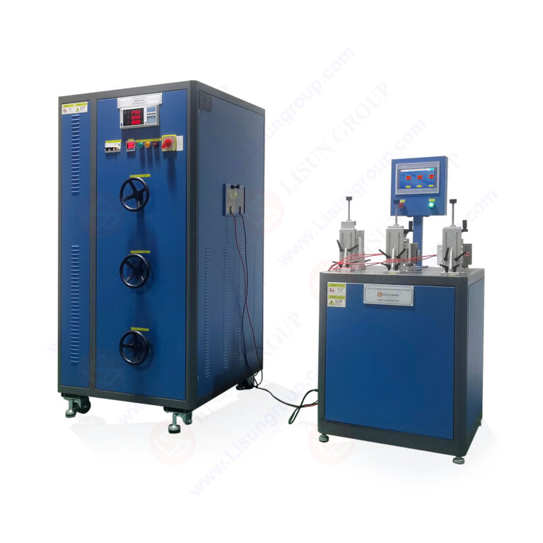
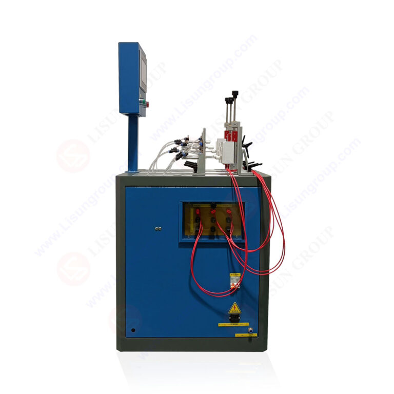
The LISUN CZKS-3 series breaking capacity testers integrate multiple subsystems to deliver comprehensive testing capabilities. The core architecture includes a PLC-based control unit, pneumatic cylinder-driven actuation system, programmable AC power supply, precision current and voltage sensors, and a data acquisition module. The CZKS-3 base model provides single-station testing for standard plugs and sockets. All models feature touch-screen HMI interfaces for parameter programming and real-time test visualization.
3.2 Model Variants and Capabilities
The CZKS-3 series encompasses three specialized variants. The CZKS-3P is optimized for testing plugs and portable socket-outlets, featuring automatic plug insertion with adjustable insertion depth and angle. The CZKS-3S focuses on switch durability testing, incorporating multidirectional actuation that simulates toggle, rocker, and push-button switch operations. The CZKS-3A handles automotive and industrial connectors, offering extended current ranges up to 50A and environmental chamber integration for temperature-controlled testing. Each variant maintains the same PLC backbone, enabling standardized data reporting across different test scenarios.
3.3 Technical Specifications Comparison
| Parameter | CZKS-3 | CZKS-3P | CZKS-3S | CZKS-3A |
|---|---|---|---|---|
| Test Voltage Range | 100–300V AC | 100–300V AC | 100–300V AC | 100–500V AC |
| Test Current Range | 1–32A | 1–32A | 1–25A | 1–50A |
| Power Factor Adjustment | 0.5–1.0 | 0.5–1.0 | 0.5–1.0 | 0.4–1.0 |
| Actuation Type | Pneumatic cylinder | Pneumatic cylinder | Electromagnetic + pneumatic | Pneumatic cylinder |
| Number of Test Stations | 1 | 1 | 2 | 1 |
| Max Operations per Cycle | 999 | 999 | 999 | 999 |
| Data Sampling Rate | 10 kHz | 10 kHz | 20 kHz | 10 kHz |
4.1 Pre-Test Sample Preparation and Mounting
Before initiating breaking capacity tests, samples must be conditioned according to standard requirements. Plugs and sockets undergo visual inspection for mechanical defects, dimensional verification per IEC 60884-1 Clause 9, and baseline insulation resistance measurement at 500V DC. Mounting fixtures on the CZKS-3 series systems accommodate multiple connector form factors, including flat pins, round pins, and grounding configurations. The CZKS-3P model includes adjustable clamping mechanisms that apply consistent mechanical pressure across the plug-socket interface, eliminating variability from operator handling.
4.2 Electrical Parameter Programming
The test parameters are programmed through the CZKS-3 series HMI interface, which supports both manual entry and standard template-based configuration. Operators set test voltage, current, power factor, number of operations, on-time and off-time durations, and failure criteria. For IEC 60884-1 compliance testing, a typical configuration includes 250V test voltage, 16A test current, 0.6 power factor, and 50 make-break cycles with 5-second intervals. The system automatically calculates the required reactive power compensation to achieve the target power factor, adjusting inductive or capacitive loading as needed.
4.3 Real-Time Monitoring and Data Acquisition
During test execution, the CZKS-3 series continuously monitors voltage and current waveforms at 10 kHz sampling rates, capturing transient events such as arc initiation and extinction. The data acquisition system records peak current, arc duration, contact resistance changes, and voltage drop across the contacts. The CZKS-3S model offers enhanced 20 kHz sampling specifically for switch transient analysis. All captured data is stored in CSV format for post-test analysis, with automatic pass/fail criteria evaluation based on user-defined thresholds for maximum arc duration (typically <5 ms) and contact temperature rise (<65°C).
5.1 Household Plug and Socket Testing
Manufacturers of household electrical accessories routinely use the CZKS-3 series for type testing and production quality control. A typical application involves testing 16A rated plugs per IEC 60884-1, where each sample undergoes 50 breaking cycles under full rated load. The CZKS-3P model automates the entire sequence, reducing test time from 30 minutes manually to under 10 minutes per sample. Data collected during these tests helps manufacturers identify design weaknesses such as inadequate contact pressure, insufficient arc quenching gaps, or suboptimal pin geometry.
5.2 Switch Durability Verification
Switch manufacturers leverage the CZKS-3S for verifying switch breaking capacity per IEC 60669-1 and IEC 61058-1. The system tests toggle switches, rocker switches, and push-button switches through their full mechanical life cycles while monitoring electrical performance. For automotive switch applications, the CZKS-3A model simulates high-inrush current conditions typical of headlamp and wiper motor circuits. The ability to program multi-step test sequences allows engineers to evaluate switch performance under combined electrical and thermal stress conditions.
5.3 Compliance Verification for Global Markets
Testing laboratories and certification bodies rely on the CZKS-3 series for conducting compliance testing according to multiple international standards. The system’s programmable parameters enable seamless switching between IEC, GB/T, and UL testing protocols. For example, a single unit can test plugs to IEC 60884-1 in the morning and automotive connectors to ISO standards in the afternoon. The CZKS-3A variant includes a calibration mode that meets ISO/IEC 17025 requirements for laboratory accreditation, ensuring traceable measurements for certification reports.
6.1 Waveform Analysis Techniques
Post-test analysis of captured voltage and current waveforms reveals critical failure indicators. Normal breaking events exhibit a clean current zero crossing with minimal arcing, typically lasting less than 2 milliseconds. Abnormal events show extended arc durations, multiple reignitions, or current chopping—a condition where the current is interrupted before natural zero crossing. The CZKS-3 series software performs automated waveform analysis, flagging events that exceed user-defined thresholds. Engineers examine these flagged events to distinguish between acceptable contact wear and impending failure conditions.
6.2 Common Failure Modes in Breaking Capacity Tests
Contact adhesion, also known as contact welding, represents the most severe failure mode during breaking capacity testing. This occurs when the arc melts contact material, forming a metallic bridge that prevents circuit interruption. The CZKS-3 series detects adhesion through continuous current monitoring after the actuation signal—if current persists beyond 50 milliseconds of contact separation, the system records a failure and immediately terminates the test. Other failure modes include excessive contact erosion measured by mass loss post-test, insulation breakdown detected through dielectric strength testing, and mechanical jamming caused by softened plastic housing components.
6.3 Statistical Data Reporting
The CZKS-3 series generates comprehensive test reports including statistical summaries of all measured parameters. Reports display minimum, maximum, and average values for arc duration, peak current, and contact resistance across test cycles. Trend analysis graphs show degradation patterns over the test sequence, allowing engineers to predict service life under normal operating conditions. The software exports data in formats compatible with Minitab and other statistical analysis tools, enabling design of experiments (DOE) studies for optimizing contact geometry and material selection.
7.1 Sample Size and Statistical Significance
For reliable breaking capacity evaluation, statistical sampling plans should follow standards such as IEC 60447 for low-voltage switchgear. A minimum of three samples per test condition is recommended, with five to ten samples preferred when evaluating design changes. The CZKS-3 series supports batch testing with automatic sample changeover, allowing operators to program multiple test sequences and walk away. Data from batch tests enables calculation of Weibull distribution parameters for reliability modeling.
7.2 Environmental Control Considerations
Breaking capacity test results are sensitive to ambient temperature and humidity conditions. Testing should be conducted in controlled environments at 23°C ± 5°C and 50% ± 20% relative humidity per standard requirements. The CZKS-3A model includes optional environmental chamber integration for testing at elevated temperatures (up to 85°C) or sub-zero conditions (down to -40°C), simulating automotive under-hood or outdoor installation scenarios. Temperature sensors embedded in the test fixtures monitor contact temperature rise, ensuring that thermal effects are accurately captured.
7.3 Maintenance and Calibration Protocols
To maintain measurement accuracy, the CZKS-3 series requires periodic calibration of current and voltage sensors, typically every 12 months or after 10,000 test cycles. Pneumatic actuation systems need regular lubrication and seal replacement to maintain consistent actuation forces—a critical parameter because inconsistent contact separation speed affects arc characteristics. The control unit includes self-diagnostic routines that verify sensor drift and actuation timing before each test sequence.
The plug socket breaking capacity test represents a fundamental safety verification procedure for electrical connectors used in household, industrial, and automotive applications. This guide has demonstrated that proper implementation of breaking capacity testing requires understanding of the electrical stress parameters, international standards requirements, and appropriate test equipment capabilities. The LISUN CZKS-3 series, including the CZKS-3, CZKS-3P, CZKS-3S, and CZKS-3A models, provides comprehensive solutions for conducting breaking capacity tests in accordance with IEC 60884-1, IEC 60669-1, IEC 61058-1, and GB/T 2099.1 standards. Key takeaways include the importance of proper test parameter configuration, real-time monitoring for failure detection, and systematic data analysis for design improvement. Manufacturers and testing laboratories benefit from the CZKS-3 series’ automated operation, precise electrical control, and comprehensive data reporting capabilities. By implementing the testing methodologies and best practices outlined in this guide, organizations can ensure their electrical connectors meet breaking capacity requirements, reducing product liability risks and enhancing user safety. The CZKS-3 series systems deliver the technical performance and standards compliance support necessary for rigorous quality assurance programs in the electrical components industry.
Q1: What is the difference between breaking capacity and normal operational current rating in plug socket testing?
A: Breaking capacity refers to the maximum current a plug or socket can safely interrupt under fault conditions, while normal operational current rating indicates the continuous current the connector can carry without overheating. Breaking capacity tests apply currents at 1.25 to 1.5 times the rated current at reduced power factor (0.6 inductive) to simulate worst-case fault scenarios. The LISUN CZKS-3 series testers are specifically designed to generate these elevated stress conditions, with programmable current ranges up to 50A and precise power factor control. During breaking capacity testing, the connector must open the circuit cleanly without sustained arcing, contact welding, or insulation damage, whereas normal operation tests verify thermal stability under rated load for extended periods. The distinction is critical because a connector might handle rated current indefinitely but fail catastrophically under fault conditions if breaking capacity is inadequate.
Q2: How does the CZKS-3S model differ from the CZKS-3P model for switch testing applications?
A: The CZKS-3S model is optimized for switch durability testing with dual-station capability, allowing simultaneous testing of two switch samples. It features electromagnetic and pneumatic combined actuation that simulates various switch operator types including toggle, rocker, and push-button mechanisms. The CZKS-3S also offers higher data sampling rates at 20 kHz specifically tuned for capturing switch contact transient behavior. In contrast, the CZKS-3P model focuses on plug and socket testing with single-station operation and automatic plug insertion mechanisms that replicate human insertion and withdrawal patterns. The CZKS-3P includes adjustable insertion depth and angle controls for testing plugs with grounding features or specialized geometries. While both models share the same PLC control architecture and data acquisition backbone, the CZKS-3S includes specialized switch mounting fixtures and programmable multi-axis actuation profiles that are not required for plug socket testing.
Q3: What are the most common failure modes detected during breaking capacity testing, and how does the CZKS-3 series identify them?
A: The most common failure modes include contact adhesion (welding), where arc energy melts contact material creating a permanent bridge; this is detected by the CZKS-3 series through continuous current monitoring—if current flow persists beyond 50 milliseconds after contact separation command, the system records a failure. Excessive arcing, defined as arc duration exceeding 5 milliseconds, indicates insufficient arc quenching gap or contact material degradation. The system captures arc duration from high-speed voltage and current waveform analysis. Contact erosion is measured through post-test sample mass comparison and contact resistance trending across test cycles. Insulation breakdown occurs when arc byproducts deposit conductive carbon tracks across insulating surfaces; the CZKS-3 series identifies this through dielectric strength testing conducted automatically between test sequences. Mechanical failures such as jamming or deformation are detected through position sensor feedback during actuation cycles, with the system flagging any deviation from expected movement patterns.
Q4: What calibration requirements apply to the CZKS-3 series for ISO/IEC 17025 laboratory accreditation?
A: For ISO/IEC 17025 accreditation, the CZKS-3 series requires annual calibration of voltage and current measurement channels against traceable reference standards. Current sensors must be calibrated from 10% to 100% of full-scale range at multiple power factor settings (0.5, 0.6, 0.8, and 1.0) because power factor affects measurement accuracy. The pneumatic actuation system requires force calibration using certified load cells to verify consistent contact separation speed. Timing circuits for arc duration measurement need verification using a precision pulse generator at 1 ms, 5 ms, and 10 ms intervals. The CZKS-3A model includes a built-in calibration mode that guides technicians through verification procedures, storing calibration coefficients and uncertainty calculations. Documentation requirements include calibration certificates, measurement uncertainty budgets, and intermediate check records performed between full calibrations—typically every three months or after 10,000 test cycles.
Q5: Can the CZKS-3 series test connectors with different plug pin configurations and international plug types?
A: Yes, the CZKS-3 series accepts interchangeable mounting fixtures accommodating various plug pin configurations including European Schuko, British BS 1363, Chinese GB/T 1002, and American NEMA 5-15 connectors. The CZKS-3P model includes adjustable clamping mechanisms that accommodate pin diameters from 1.5 mm to 6 mm and pin spacings from 10 mm to 25 mm. For testing socket-outlets, the system provides modular socket-mounting plates that can be swapped between test sessions. The automated plug insertion mechanism supports insertion depths from 5 mm to 25 mm with programmable insertion and withdrawal speeds from 10 mm/s to 100 mm/s. The CZKS-3A model additionally accommodates automotive pin configurations including blade-type and round-pin connectors with current ratings up to 50A. All mounting fixtures are designed for quick-change operation, typically taking less than two minutes to reconfigure between different connector types.