









Here is the technical article generated according to your specifications.
Abstract
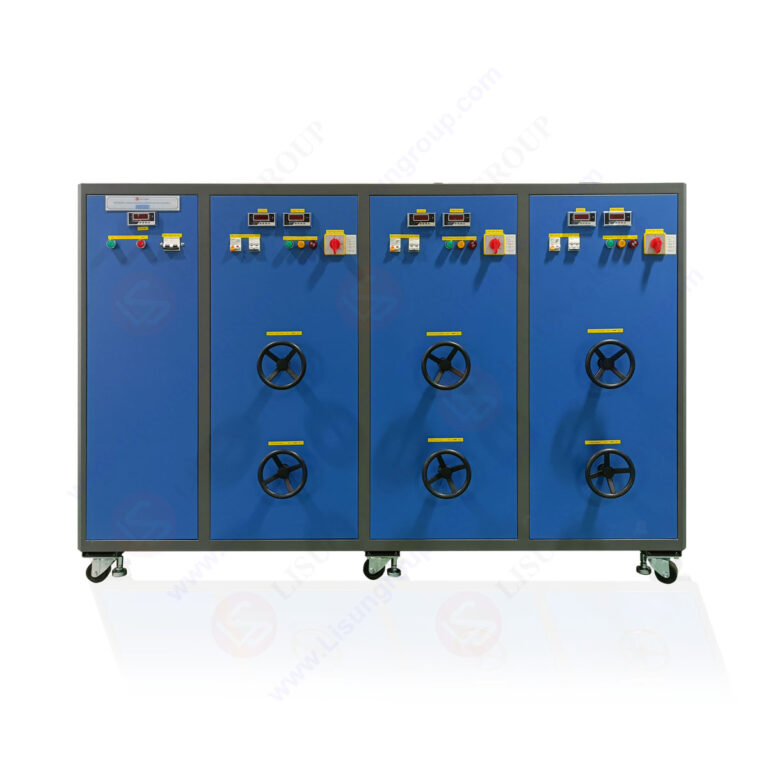
This article provides a technical analysis of the LISUN DFX series Externally Ballasted Fluorescent Lamp Test Load Cabinet, a critical instrument for power cord life and load testing. Designed for electrical accessory compliance, the DFX series simulates the precise inductive, resistive, and capacitive characteristics of ballasted lighting loads. For quality control engineers and testing laboratories, this device is essential for validating the durability of switches, sockets, and connectors against international standards. This article details the load test cabinet’s technical specifications, model comparisons, and integration capabilities, demonstrating its role in rigorous durability validation for power cords and electrical accessories.
1.1 The Necessity of Reactive Load Simulation
Standard resistive loads do not replicate the high inrush currents and arcing conditions caused by inductive ballasts. A power cord must withstand these stresses without failure. The LISUN DFX series provides a load test cabinet that generates the exact electrical profile required by IEC and GB standards, ensuring that tests on switches and outlets reflect real-world conditions.
1.2 Core Application in Durability Validation
The primary function of the DFX series is to provide a stable, externally ballasted load for endurance testing. Power cord life and load testing protocols require thousands of cycles at rated current. This cabinet maintains consistent power factor and waveform integrity, which is critical for repeatable results.
2.1 Load Simulation Capabilities
The DFX series employs a combination of high-precision inductors, resistors, and capacitors. It achieves a power factor (PF) range of 0.3 to 0.9, with a resolution of 0.01. This allows engineers to model loads for fluorescent lamps, LED drivers, and other ballasted equipment with high accuracy.
2.2 Measurement and Control Precision
The cabinet integrates a digital data acquisition system with ±0.5% accuracy for voltage and current measurements. The output current is continuously adjustable, typically ranging from 0.1 A to 80 A (model-dependent), with a crest factor maintained between 1.4 and 1.7 to simulate realistic harmonics.
3.1 Selection Criteria for Different Testing Loads
Choosing the correct model depends on the rated current of the device under test (DUT). The DFX-20 is suitable for small switches, while the DFX-80 is designed for high-current industrial connectors. The power cord life and load testing capabilities scale with the model’s maximum current output.
3.2 Technical Comparison Table: LISUN DFX Series Models
| Model | Max Current (A) | Channels | Input Voltage (V AC) | Load Type | Application Focus |
|---|---|---|---|---|---|
| DFX-20 | 20 | 1 | 220/110 | Inductive/Resistive | Small switches, IEC 60669-1 |
| DFX-20-3CH | 20 | 3 | 220/110 | Inductive/Resistive | Multi-pole switches, 3-phase |
| DFX-40 | 40 | 1 | 220/110 | Inductive/Resistive | Standard sockets, IEC 60884-1 |
| DFX-60 | 60 | 1 | 220/110 | Inductive/Resistive | Heavy-duty connectors |
| DFX-80 | 80 | 1 | 380/220 | Inductive/Resistive | Industrial power cords |
4.1 Alignment with IEC and GB Regulations
The DFX series is engineered to meet strict standard requirements. For example, IEC 60669-1 Clause 19.2 mandates endurance testing for switches with a specified load power factor. The DFX series adjusts the PF to 0.6 ± 0.05 for inductive loads, directly fulfilling this clause.
4.2 Standard Validation Reference Table
| Standard | Relevant Clause | DFX Series Compliance Feature |
|---|---|---|
| IEC 60884-1 | Clause 20 (Endurance) | Provides consistent 1.25x rated current for 10,000 cycles |
| IEC 60669-1 | Clause 19.2 (Load PF) | Adjustable PF from 0.3 to 0.9 for ballasted loads |
| GB/T 2099.1 | Clause 21 (Temperature) | Stable load output for heat rise testing |
| IEC 60947-1 | Clause 8.3 | High-current capability for low-voltage switchgear |
5.1 Synergy with the CZKS Series Life Testers
The load test cabinet integrates seamlessly with the LISUN CZKS series switch life testers. The CZKS controls the mechanical actuation (on/off cycles) while the DFX provides the electrical load. This creates an automated system for power cord life and load testing, reducing operator intervention and ensuring cycle consistency.
5.2 Mechanical Stress Simulation with SW-6
For comprehensive durability validation, the DFX series is often paired with the LISUN SW-6 bending tester. While the DFX simulates electrical stress, the SW-6 applies mechanical flexing to the power cord. This combined workflow verifies that the load-handling capability is not compromised by physical strain, which is critical for compliance with IEC 60884-1.
6.1 Initial Setup and Configuration
- Step 1: Connect the DUT (power cord or switch) in series with the load cabinet.
- Step 2: Select the desired current and power factor on the DFX control panel (e.g., 16 A @ PF 0.6).
- Step 3: Synchronize the mechanical life tester (e.g., CZKS-10) to the DFX series.
6.2 Data Acquisition and Validation
During the test, the DFX series monitors voltage drop and current stability. Any deviation beyond ±2% triggers an automatic alarm, conforming to the failure criteria defined in IEC standards. This real-time monitoring is the core of modern power cord life and load testing.
7.1 Heat Dissipation and Stability
Unlike internal solid-state loads, the external ballast in the DFX series dissipates heat efficiently. This prevents thermal drift, ensuring that the load impedance remains constant over thousands of test cycles. For loads requiring up to 80 A, this stability is non-negotiable for valid results.
7.2 Waveform Purity
The inductive-capacitive (L-C) network provides a sinusoidal current waveform. Solid-state loads often introduce harmonic distortion. The DFX series maintains a total harmonic distortion (THD) of less than 3%, which is essential for simulating the behavior of real fluorescent ballasts.
The LISUN DFX series Externally Ballasted Fluorescent Lamp Test Load Cabinet is a fundamental tool for any laboratory conducting power cord life and load testing. Its ability to generate precise inductive loads, coupled with models ranging from 20 A to 80 A, ensures compliance with IEC 60669-1, IEC 60884-1, and GB standards. The technical accuracy of its load simulation—with a PF resolution of 0.01 and low THD—validates the durability of switches and connectors under the most stringent conditions. When integrated with LISUN’s CZKS and SW-6 testers, it forms a complete, automated workflow that delivers reliable, repeatable data for compliance certification. For engineers and test managers, investing in this load test cabinet means eliminating guesswork from lifecycle analysis and achieving faster, more defensible product approval.
Q1: How do I select the correct DFX model for my power cord life and load testing application?
A: The selection is primarily based on the rated current of your Device Under Test (DUT). For standard household switches (rated up to 10A or 16A), the DFX-20 or DFX-20-3CH is sufficient for power cord life and load testing. For socket outlets tested per IEC 60884-1 Clause 20, the DFX-40 is common. If you are testing industrial connectors or heavy-duty power cords with ratings above 32A, you require the DFX-60 or DFX-80. The DFX-20-3CH is specifically designed for three-pole switches, allowing simultaneous testing of multiple poles, which is vital for compliance with IEC 60669-1 for multi-gang switches. Always ensure your test current does not exceed 80% of the cabinet’s maximum rated output to avoid thermal stress on the load ballasts.
Q2: Can the DFX series simulate loads for LED drivers or is it only for fluorescent lamps?
A: While primarily designed with an externally ballasted inductive load for fluorescent lamps, the DFX series is highly effective for testing LED drivers and other electronic loads. The key is its adjustable power factor. An LED driver presents a highly non-linear load, but the IEC standards for switches and connectors often require testing with a defined inductive load (PF 0.6). The DFX series is the standard tool for this. For testing the driver itself, the cabinet’s resistive/inductive network can be set to simulate the equivalent load of a light source. For pure electronic load testing (with inrush current simulation), consider the LISUN ECL series. The DFX remains the industry standard for accessory endurance testing.
Q3: What are the maintenance requirements for the LISUN DFX load test cabinet?
A: The DFX series is built with heavy-duty air-core inductors and wire-wound resistors, requiring minimal maintenance. The primary maintenance task is ensuring adequate airflow for heat dissipation. The air filters on the cabinet’s rear panel should be cleaned quarterly to prevent dust accumulation, which can raise internal temperatures and affect load stability. Calibration of the internal ammeter and voltmeter is recommended annually, using a calibrated external multimeter (0.1% accuracy). The contactors inside the cabinet for selecting load taps should be visually inspected every 10,000 test cycles for signs of arcing. For power cord life and load testing, maintaining the cleanliness of the high-current connectors on the front panel is critical to prevent voltage drops.
Q4: How does the DFX series handle the high inrush current typical of ballasted loads?
A: This is a core feature of the DFX series. When a fluorescent lamp or ballast is started, the inrush current can be 5 to 15 times the steady-state current. The externally ballasted design of the DFX cabinet naturally replicates this phenomenon because it uses actual magnetic ballasts. The internal circuitry is designed to handle these transient currents without entering protection mode, unlike many programmable AC power sources. The cabinet’s current measurement system is also fast-sampling, capable of capturing the first peak of the inrush current. This provides critical data for engineers analyzing contact welding in switches during power cord life and load testing, a requirement often implied by the “abnormal operation” clauses in IEC 60669-1.