









Precision AC/DC Power Meter with RS232/RS485 for LED & Automotive Testing: A Technical Guide for Compliance and Accuracy
Abstract
The Precision AC/DC Power Meter with RS232/RS485 for LED & Automotive Testing represents a critical advancement in electrical measurement instrumentation for compliance-driven industries. These digital power meters combine high-accuracy digital sampling waveform analysis with automatic range switching to deliver reliable power measurements across AC and DC systems. Designed for LED manufacturing quality control and automotive electronics validation, these instruments support harmonic analysis up to the 50th order, comply with EN/IEC61000-3-2 and LM-79 standards, and offer wide frequency measurement from 0.5Hz to 100kHz. With robust RS232/RS485 communication interfaces, they integrate seamlessly into automated test systems. This article examines the technical architecture, measurement capabilities, compliance benefits, and practical applications of precision AC/DC power meters across LED and automotive testing environments.
1. Core Architecture of Precision Digital Power Meters
1.1 Digital Sampling Waveform Analysis Technology
Modern precision AC/DC power meters employ digital sampling waveform analysis as their foundational measurement technique. Unlike analog instruments that rely on rectification and averaging circuits, digital sampling systems capture instantaneous voltage and current values at high sampling rates, typically exceeding 100kS/s per channel. These sampled data points undergo mathematical processing using Fast Fourier Transform (FFT) algorithms to decompose complex waveforms into fundamental and harmonic components. This approach enables simultaneous measurement of true RMS voltage, true RMS current, active power, apparent power, reactive power, power factor, and displacement factor from a single acquisition cycle. The digital architecture eliminates errors associated with waveform distortion, allowing accurate measurements even when signals contain significant harmonic content, a common condition in LED driver circuits and automotive power electronics.
1.2 Automatic Range Switching Mechanism
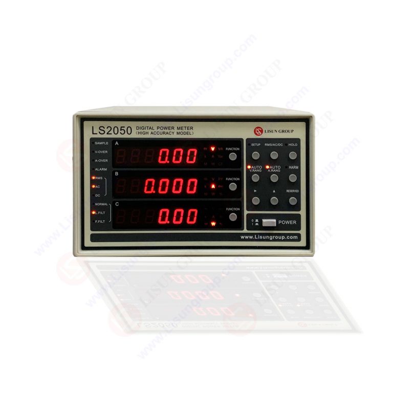
Automatic range switching represents a critical engineering feature that balances measurement resolution with overload protection. The LS2050 series implements a multi-range front-end design that continuously monitors input signals and selects the optimal voltage and current ranges without interrupting the measurement process. When the input signal approaches 90% of the current range’s full-scale value, the system transitions to the next higher range; conversely, when the signal drops below 10% of full scale, it switches to a lower range for improved resolution. This dynamic ranging capability spans from millivolt and microamp levels up to 1600V instantaneous maximum voltage and 50A instantaneous maximum current. The switching hysteresis prevents oscillation at boundary conditions, ensuring stable readings during transient events common in automotive load testing and LED driver startup sequences.
1.3 Harmonic Analysis Engine (0-50th Order)
The harmonic analysis engine in precision AC/DC power meters provides spectral decomposition of current and voltage waveforms up to the 50th harmonic order, compliant with both IEC and CSA methods. For each harmonic component, the instrument calculates magnitude, phase angle, and total harmonic distortion (THD) percentage relative to the fundamental frequency. The analysis engine applies anti-aliasing filters before sampling and uses windowing functions such as Hanning or Blackman-Harris to minimize spectral leakage effects. This capability is essential for EN/IEC61000-3-2 compliance testing, where limits are specified for individual harmonic currents up to the 40th order for class C equipment (lighting) and class D equipment (automotive electronics). The instrument displays harmonic data numerically and graphically, showing bar charts of harmonic content alongside total distortion metrics.
2. Measurement Capabilities and Technical Specifications
2.1 AC/DC Voltage and Current Measurement
Precision AC/DC power meters offer comprehensive voltage and current measurement across DC and AC systems with frequency ranges from 0.5Hz to 100kHz. Table 1 below compares the measurement specifications across the LS2050 series models.
Table 1: Comparative Technical Specifications of LS2050 Series Precision Power Meters
| Parameter | LS2050B (Standard Accuracy) | LS2050C (High Accuracy) | LS2050C-IEC (EMC Harmonic) |
|---|---|---|---|
| Voltage Accuracy (DC) | ±0.1% of reading + 0.1% of range | ±0.05% of reading + 0.05% of range | ±0.05% of reading + 0.05% of range |
| Voltage Accuracy (AC, 45-65Hz) | ±0.2% of reading + 0.1% of range | ±0.1% of reading + 0.1% of range | ±0.1% of reading + 0.1% of range |
| Current Accuracy (DC) | ±0.1% of reading + 0.1% of range | ±0.05% of reading + 0.05% of range | ±0.05% of reading + 0.05% of range |
| Power Accuracy (45-65Hz) | ±0.2% of reading + 0.1% of range | ±0.1% of reading + 0.1% of range | ±0.1% of reading + 0.1% of range |
| Harmonic Analysis | Up to 50th order (IEC method) | Up to 50th order (IEC/CSA) | Up to 50th order (IEC/CSA) |
| Bandwidth | DC to 100kHz | DC to 100kHz | DC to 100kHz |
| Compliance Standards | General testing | High-accuracy R&D | EN/IEC61000-3-2 |
The wide bandwidth from DC through 100kHz accommodates PWM signals in automotive inverters, high-frequency LED drivers, and switched-mode power supplies. True RMS conversion remains accurate for waveforms with crest factors up to 3:1 at full scale and 6:1 at half scale, handling the high peak-to-average ratios characteristic of modern power electronics.
2.2 Power, Power Factor, and Displacement Factor
Active power measurement in these instruments employs the digital multiplication method: instantaneous voltage and current samples are multiplied and averaged over one or more complete cycles. For sinusoidal systems, apparent power (VA) equals the product of RMS voltage and RMS current, while reactive power (VAR) is derived from the quadrature component. Power factor (PF) is calculated as the ratio of active power to apparent power, and displacement factor (DPF) represents the cosine of the phase angle between the fundamental voltage and current components. In non-sinusoidal conditions common with LED drivers, PF and DPF diverge significantly; the instrument reports both values independently. For automotive testing, PF measurements help evaluate the efficiency of DC-DC converters and motor controllers, while DPF analysis supports power quality assessments per IEEE 1459 standards.
2.3 Frequency Measurement from 0.5Hz to 100kHz
Frequency measurement employs zero-crossing detection with digital filtering to reject noise-induced false triggers. The instrument measures frequency on voltage or current channels with resolution down to 0.01Hz below 100Hz and 0.1Hz at higher frequencies. For frequencies below 0.5Hz, the measurement algorithm extends the observation window to multiple cycles, though response time increases proportionally. This wide frequency range covers automotive applications such as alternator output (50Hz to 400Hz), electric motor drive signals (1Hz to 1kHz), and wireless power transfer systems (10kHz to 100kHz). In LED testing, frequency measurement verifies driver output stability and helps identify resonance conditions in dimming circuits.
3. RS232/RS485 Communication and System Integration
3.1 Communication Protocol Architecture
The RS232 and RS485 communication ports on precision AC/DC power meters enable automated data acquisition and remote instrument control. RS232 provides point-to-point serial communication at baud rates from 9600 to 115200 bps, suitable for direct connection to a single computer or controller over distances up to 15 meters. RS485 supports multi-drop networks with up to 32 instruments on a single bus, extending communication distances to 1200 meters, making it ideal for production line configurations where multiple power meters monitor different test stations simultaneously. Both ports use a standardized command set based on SCPI (Standard Commands for Programmable Instruments) syntax, allowing interoperability with LabVIEW, MATLAB, Python, and proprietary test executive software.
3.2 Automated Test System Integration
Integrating precision AC/DC power meters into automated test systems provides significant throughput improvements for manufacturing environments. The instrument supports continuous streaming of measurement data at rates up to 20 readings per second for single-phase measurements, or 10 readings per second when measuring all parameters including harmonics. Trigger modes include immediate, bus-triggered, external trigger input, and timer-based acquisition, synchronizing measurements with external events such as product power-up sequences or mechanical handling operations. For LED production testing, this enables 100% inspection of each unit’s power consumption, power factor, and harmonic current at a rate of one test cycle every 2-3 seconds. In automotive electronics validation, synchronized multi-channel measurements capture power parameters across multiple vehicle subsystems during dynamic test profiles.
3.3 Data Logging and Remote Monitoring
On-board data logging capabilities store up to 10,000 measurement records with time stamps in non-volatile memory. Users configure logging intervals from 10ms to 3600 seconds, capturing trends in power consumption, voltage stability, and harmonic evolution during long-duration tests such as LED lumen maintenance or automotive battery discharge cycles. The RS485 interface facilitates remote monitoring dashboards where plant-wide energy consumption patterns are aggregated and analyzed. For EMC compliance laboratories, continuous harmonic monitoring across the RS232 port provides real-time feedback during EN/IEC61000-3-2 pre-compliance testing, allowing immediate identification of harmonic limits violations without waiting for post-processing analysis.
4. Compliance Testing for LED Manufacturing
4.1 EN/IEC61000-3-2 Harmonic Current Compliance
For LED lighting manufacturers, compliance with EN/IEC61000-3-2 is mandatory for CE marking and market access in European Economic Area countries. The standard limits harmonic currents injected into the public low-voltage supply system, classifying LED lamps as Class C equipment with the most stringent limits. The LS2050C-IEC model provides dedicated harmonic analysis software that automates the compliance assessment process. The instrument measures each harmonic current from the 2nd through the 40th order, compares measured values against class C limits with appropriate headroom calculations, and generates pass/fail reports according to the standard’s statistical evaluation procedure. The analysis includes both absolute current limits and percentage-of-fundamental limits, applying the most restrictive requirement at each harmonic order. For multi-chip LED arrays and tunable white fixtures, the instrument captures harmonic variations across different operating modes and dimming levels.
4.2 LM-79 Electrical Measurements for SSL Products
LM-79, published by the Illuminating Engineering Society (IES), specifies the electrical and photometric measurement methods for solid-state lighting (SSL) products. For electrical measurements, LM-79 requires measurement of input voltage, input current, active power, power factor, and total harmonic distortion under steady-state conditions after a thermal stabilization period. Precision AC/DC power meters meet the LM-79 accuracy requirements by providing better than ±0.2% reading accuracy for voltage, current, and power measurements. The instrument calculates total harmonic distortion for both voltage and current using the formula THD = sqrt(Σ(V_h²)/V_1²) × 100%, where h ranges from 2 to 50. The RS232 port outputs measurement data directly to goniophotometer software, creating synchronized electrical and photometric reports that satisfy LM-79 documentation requirements for product certification programs such as ENERGY STAR (United States) and DLC (DesignLights Consortium, Canada).
5. Automotive Electronics Validation
5.1 Power Quality Analysis for Vehicle Electrical Systems
Modern automotive electrical systems operate at multiple voltage levels: 12V and 24V for conventional systems, 48V for mild hybrids, and 300V-800V for electric and plug-in hybrid vehicles. Precision AC/DC power meters validate power quality across all these voltage domains by measuring DC ripple voltage, voltage droop during load surges, and transient response characteristics per ISO 16750-2 and LV 124 standards. The instrument’s wide bandwidth captures ripple frequencies up to 100kHz from switched-mode power supplies and motor controllers. For electric vehicle onboard chargers, the meter measures AC input parameters (voltage, current, power, power factor, harmonics) simultaneously with DC output parameters (voltage, current, power, efficiency) using dual-channel configuration. The RS485 interface enables communication with battery management systems (BMS) and vehicle control units (VCU) for synchronized data acquisition during vehicle-level validation tests.
5.2 EMC Pre-Compliance Testing for Automotive Components
Automotive EMC requirements per CISPR 25 and ISO 11452-1 establish limits for conducted and radiated emissions from electronic subassemblies. While these standards primarily address RF emissions, conducted harmonics on power lines provide early indicators of EMC issues. Precision AC/DC power meters with harmonic analysis capability serve as pre-compliance screening tools, identifying power quality problems that could generate broadband conducted emissions. For components such as LED headlamps, infotainment systems, and electronic control units (ECUs), the instrument measures harmonic currents up to 50th order while the device operates under load. Exceedances in specific harmonic bands correlate with known emission mechanisms: 2nd and 3rd harmonics indicate rectifier and switching stage issues, 5th through 11th harmonics suggest input filter problems, and higher-order harmonics point to control loop instabilities. This pre-compliance screening reduces the number of formal EMC test iterations, saving significant time and cost during product development cycles.
6. R&D Power Quality Analysis Applications
6.1 Efficiency Optimization for Power Converters
In R&D environments, precision AC/DC power meters enable detailed efficiency characterization of power converters, including AC-DC adapters, DC-DC converters, and DC-AC inverters. Accurate efficiency measurement requires simultaneous measurement of input and output power with sufficient accuracy to resolve sub-percent differences. The LS2050C model’s ±0.05% reading accuracy for DC power measurements provides the necessary resolution for efficiency calculations. Engineers use the instrument’s measurement capabilities to map efficiency across load ranges from 10% to 110% of rated output, identifying optimal operating points and efficiency reduction mechanisms. For automotive DC-DC converters, the power meter measures efficiency under dynamic load profiles that simulate real driving conditions, including acceleration, regenerative braking, and auxiliary load activation. The harmonic analysis function identifies switching frequency components and their sidebands, guiding filter design improvements to reduce electromagnetic interference while maintaining conversion efficiency.
6.2 Standby Power and No-Load Loss Measurement
International energy efficiency regulations require standby power consumption below 0.5W for many electronic devices, with some categories targeting 0.1W or lower. Measuring such low power levels presents significant accuracy challenges because voltage and current waveforms may become highly distorted at no-load conditions, and phase angles approach 90 degrees. Precision AC/DC power meters overcome these challenges through automatic range switching that selects the most sensitive current range (often 10mA or 5mA full scale) and through specialized low-power measurement algorithms that minimize phase error at high power factors. The instruments achieve power measurement accuracy better than ±0.5% of reading even at 0.1W power levels, meeting the requirements of IEC 62301 standby power measurement standard. For LED drivers in automotive interior lighting, no-load loss measurements guide transformer and controller design improvements that extend battery life during vehicle parking periods.
7. Safety and Overload Protection Design
7.1 High Overload Capacity and Protection Circuits
Precision AC/DC power meters incorporate robust protection circuits that safeguard measurement electronics against transient overvoltage conditions common in industrial environments. The LS2050 series withstands instantaneous maximum voltage of 1600V peak and instantaneous maximum current of 50A peak without damage, though accuracy specifications apply only within the normal measurement range. Protection architecture includes metal oxide varistors (MOVs) across input terminals for voltage surge clamping, fast-acting fuses in series with current inputs, and optoisolated digital interfaces that prevent ground loop currents from damaging communication ports. For automotive testing where 48V and 12V systems may experience load dump events up to 7V above nominal, the protection circuits ensure continuous operation without measurement interruption. The instrument complies with IEC 61010 (safety requirements for electrical equipment for measurement, control, and laboratory use) and UL 1989 (standard for power supplies and chargers), providing certification evidence for test laboratory accreditation bodies.
7.2 Thermal Management for Continuous Operation
Continuous-duty testing in manufacturing environments demands thermal stability to maintain measurement accuracy over extended periods. Precision AC/DC power meters employ forced-air cooling with temperature-compensated reference circuits that maintain accuracy specifications from 0°C to 40°C ambient temperature. Internal temperature sensors monitor critical components including shunt resistors, analog-to-digital converters, and voltage dividers, applying compensation coefficients stored during factory calibration. The instrument’s maximum continuous power dissipation rating determines the longest allowable measurement duration at specific voltage and current levels; for example, at 300V and 20A on a 20A range, the internal dissipation remains below 5W, allowing indefinite continuous operation. For testing scenarios that exceed continuous ratings, the instrument implements a programmable auto-stop function that terminates measurements when internal temperature approaches limits.
8. Conclusion
Precision AC/DC power meters with RS232/RS485 communication represent essential measurement instruments for electrical testing engineers in LED manufacturing and automotive electronics industries. The combination of digital sampling waveform analysis, automatic range switching, and 50th-order harmonic analysis provides comprehensive power quality assessment capabilities that support compliance with EN/IEC61000-3-2, LM-79, IEC 61010, and UL 1989 standards. The LS2050 series offers scalable accuracy levels from standard (LS2050B) through high-accuracy research-grade (LS2050C) to EMC-specific compliance testing (LS2050C-IEC), accommodating diverse requirements from production line quality control to R&D power converter optimization. The RS232 and RS485 communication interfaces enable seamless integration into automated test systems, supporting high-throughput manufacturing environments and multi-station validation setups. With wide measurement bandwidth from DC to 100kHz, overload protection up to 1600V and 50A, and temperature-compensated accuracy, these instruments deliver reliable, repeatable measurements under demanding industrial conditions. For engineers selecting power measurement equipment, the precision AC/DC power meter with RS232/RS485 for LED and automotive testing provides the technical foundation for achieving compliance, improving product efficiency, and reducing time-to-market for electronic products that must meet increasingly stringent international power quality regulations.
FAQ (Frequently Asked Questions)
Q1: What is the difference between power factor (PF) and displacement factor (DPF), and why do both matter for LED driver testing?
A: Power factor (PF) represents the ratio of active power to apparent power, accounting for both phase displacement and harmonic distortion in the current waveform. Displacement factor (DPF) specifically measures the cosine of the phase angle between the fundamental voltage and fundamental current components, ignoring harmonic content. For LED drivers with switch-mode power supplies, these values often differ significantly: typical LED drivers may show PF of 0.65 and DPF of 0.95, meaning the poor PF is primarily due to harmonic distortion rather than phase shift. EN/IEC61000-3-2 class C limits restrict harmonic currents, directly addressing the harmonic contribution to low PF. The LS2050 series measures both parameters simultaneously, enabling engineers to determine whether power factor correction should focus on phase compensation (improving DPF) or harmonic filtering (reducing current distortion). This distinction is critical for designing efficient front-end power stages for LED lighting products that must simultaneously meet harmonic limits and achieve high system efficiency.
Q2: How does the RS485 multi-drop network configuration work in a production line with multiple power meters?
A: The RS485 multi-drop network allows up to 32 LS2050 series power meters to share a single communication cable pair, with each instrument assigned a unique address from 0 to 31 via front-panel configuration. The host computer or programmable logic controller (PLC) sends commands with address headers, and only the addressed instrument responds. Bus termination resistors (typically 120Ω) at both ends of the cable prevent signal reflections. In a typical LED production line, each test station has one power meter measuring the product under test; the central computer polls each station sequentially, requesting measurement data after each test cycle completes. The industrial-grade RS485 transceivers maintain data integrity over cable lengths up to 1200 meters, suitable for multi-building campus installations. For redundancy, the LS2050 series also supports individual RS232 connections to each instrument for calibration and configuration while the RS485 network handles production data collection.
Q3: What are the critical considerations for selecting between LS2050B, LS2050C, and LS2050C-IEC for a testing laboratory?
A: The selection depends on the specific application accuracy requirements and compliance testing needs. The LS2050B (standard accuracy, ±0.2% reading for AC power) is suitable for production line pass/fail testing where absolute accuracy is less critical than repeatability and speed. The LS2050C (high accuracy, ±0.1% reading for AC power) targets R&D applications requiring precise efficiency measurements and power quality analysis where errors must be minimized. The LS2050C-IEC adds dedicated EN/IEC61000-3-2 compliance testing firmware that automates harmonic limit evaluation, generates pass/fail reports, and includes the statistical assessment (class C step-by-step). For laboratories performing formal compliance testing, the LS2050C-IEC eliminates manual data analysis and reduces testing time. Additionally, the LS2050C-IEC includes certified calibration traceable to national standards specifically for harmonic measurement accuracy. Laboratories serving multiple clients with diverse requirements may benefit from the LS2050C-IEC as the most versatile single instrument, while dedicated production lines with fixed test protocols may choose the cost-optimized LS2050B.