









Here is the technical article based on your specifications.
Abstract
Understanding the distinction between Thermal Shock vs Temperature Cycling: Key Differences Explained | LISUN is critical for engineers designing robust LED products. This article clarifies the fundamental differences in ramp rates, dwell times, and failure mechanisms associated with each test method. We explore how accelerated aging systems like the LISUN LEDLM-80PL integrate Arrhenius-based modeling to predict lumen maintenance (L70/L50) across 6,000-hour protocols. By referencing IES LM-80, TM-21, and IES LM-84 standards, we provide a data-driven framework for selecting the appropriate thermal stress test for components versus finished luminaires. This guide is essential for professionals seeking to balance test realism with accelerated failure analysis.
1.1 Defining Thermal Shock
Thermal shock testing involves transferring a specimen between two extreme temperature zones (e.g., -40°C to +125°C) within seconds. The primary goal is to induce mechanical stress from sudden thermal expansion and contraction. This rapid transition creates high strain rates at material interfaces, such as solder joints, die attach layers, and encapsulants. The test is designed to replicate failures caused by rapid weather changes or power-on conditions, focusing on mechanical integrity rather than long-term chemical degradation.
1.2 Defining Temperature Cycling
Temperature cycling, in contrast, uses controlled ramp rates (typically 1-15°C/min) with significant dwell times at temperature extremes. A standard cycle might last 2-6 hours, including heat-up, soak, and cool-down phases. The key differentiator is the slower rate of change, which allows for uniform temperature distribution across the sample. This test is designed to accelerate chemical and photochemical degradation processes, such as phosphor conversion efficiency loss and driver capacitor aging, that are highly dependent on total thermal exposure time.
1.3 The Core Distinction: Ramp Rate vs. Dwell Time
The primary technical difference between thermal shock and temperature cycling lies in the rate of change and dwell duration. Thermal shock emphasizes strain rate (often > 30°C/min), while temperature cycling emphasizes total thermal dose (integrated time at temperature). For LED testing, thermal shock is more aggressive on mechanical structures, while temperature cycling is more representative of long-term lumen depreciation. Engineers must choose based on the failure mode they intend to investigate—mechanical vs. chemical.
2.1 IES LM-80 and TM-21 for Lumen Maintenance
IES LM-80 is the standard for measuring lumen depreciation of LED sources, light engines, and luminaires. It mandates testing at multiple case temperatures (typically 55°C, 85°C, and a third user-defined point) for a minimum of 6,000 hours. TM-21 then extrapolates these results to estimate L70 (time to 70% lumen output) and L50 lifetimes. The LISUN LEDLM-80PL system is specifically designed to comply with this standard, using its integrated temperature chambers to maintain the required case temperatures. The Arrhenius model built into the software analyzes the thermal acceleration factor derived from these temperature points.
2.2 IES LM-84 and TM-28 for Integrated Components
IES LM-84 provides a methodology for measuring lumen maintenance of solid-state lighting (SSL) products, including integrated LED lamps and luminaires. TM-28 offers a projection method for these tests, using a different statistical fit than TM-21. The LISUN LEDLM-84PL variant is optimized for this standard, allowing for testing of larger form factors. This distinction is vital: LM-80 addresses the LED package itself, while LM-84 addresses the final product, which is more susceptible to thermal shock failures from driver board components.
2.3 Supporting Standards: IES LM-79-19 and CIE 127
IES LM-79-19 specifies the electrical and photometric measurements of SSL products, typically using an integrating sphere. This standard is used for photometric testing before and after thermal stress. CIE 127 provides guidelines for measuring LED intensity and total flux. In the context of thermal testing, these standards ensure that the measurement setup (e.g., self-absorption correction, ambient temperature control) is accurate. The LISUN systems integrate these measurement protocols to provide Before-and-After stress data, quantifying the impact of both thermal shock and temperature cycling on total luminous flux.
3.1 LEDLM-80PL: Dedicated for LM-80/TM-21 Compliance
The LISUN LEDLM-80PL is a high-precision instrument designed for long-term lumen maintenance testing. It supports up to 3 connected temperature chambers, enabling simultaneous testing at different case temperatures as required by IES LM-80. The system automatically records data at intervals of 0-1000 hours, 0-3000 hours, and 0-6000 hours. Key specs include the ability to handle a large number of LED samples per chamber, ensuring statistical validity. The built-in software uses the Arrhenius model to calculate acceleration factors and project L70/L50 lifetimes.
3.2 LEDLM-84PL: Dedicated for LM-84/TM-28 Compliance
The LEDLM-84PL variant is tailored for luminaire-level testing as per IES LM-84. It features a larger integrating sphere and a higher current capacity to accommodate complete lamps and luminaires. This system is critical for performing temperature cycling on assembled products. The larger thermal mass of a luminaire requires slower cycling rates to avoid non-uniform thermal stress. The LEDLM-84PL’s software supports the Projected Maintenance Curve (PMC) method from TM-28, which is different from the exponential fit used in TM-21.
3.3 Key Technical Specifications Comparison
Below is a table comparing the two primary LISUN system variants for thermal testing.
| Feature | LEDLM-80PL (Source/LED Chip) | LEDLM-84PL (Luminaire/SSL) |
|---|---|---|
| Primary Standard | IES LM-80, TM-21 | IES LM-84, TM-28 |
| Test Object | LED packages, modules, chips | LED lamps, luminaires, integrated boards |
| Temperature Chambers | Up to 3 (independent control) | Up to 2 (larger chamber volume) |
| Max Continuous Current | 1A typical (per channel) | 2A typical (per channel) |
| Measurement Integration | Small sphere (≤2m) | High-accuracy sphere (up to 2m) |
| Data Extrapolation | Exponential decay (TM-21) | Projected Maintenance Curve (TM-28) |
| Key Metric | L70/L50 at 6,000 hours | L70 at 6,000 hours |
4.1 Mechanical Failures from Thermal Shock
Thermal shock predominantly causes mechanical failures due to coefficient of thermal expansion (CTE) mismatch. Sudden temperature changes induce high shear stress at the solder joint between the LED die and the substrate, or at the bond wire interface. Common failure modes include die cracking, bond wire lift-off, and delamination of the phosphor layer. These failures are catastrophic and often result in a complete loss of light output (sudden death) rather than gradual lumen depreciation. Testing per thermal shock standards requires monitoring for functional failure, not just lumen maintenance.
4.2 Chemical Failures from Temperature Cycling
Temperature cycling accelerates chemical degradation through Arrhenius kinetics. The extended dwell times at high temperatures promote phosphor thermal quenching, silicone degradation (yellowing), and driver electrolytic capacitor evaporation. These are gradual processes that result in lumen depreciation. The Arrhenius model predicts that a 10°C rise in case temperature can halve the lifetime of the LED. The LISUN software utilizes this model to correlate test data. Temperature cycling is the appropriate test for validating TM-21 projections, as it generates the temperature stress profile needed for rate-based modeling.
4.3 Analysis Using LISUN Software
The LISUN software can analyze the failure data to determine the dominant failure mode. By comparing the failure distribution (Weibull analysis) and the shape of the lumen depreciation curve, engineers can infer if failures are mechanical (sudden shift) or chemical (gradual slope). For instance, a test group subjected to thermal shock (using the LEDLM-80PL’s fast cycle mode) that shows a sharp drop in flux within the first 500 hours indicates a CTE mismatch issue. A temperature cycled group (using standard dwell times) showing a smooth, exponential decay confirms a chemical aging problem.
5.1 When to Use Thermal Shock
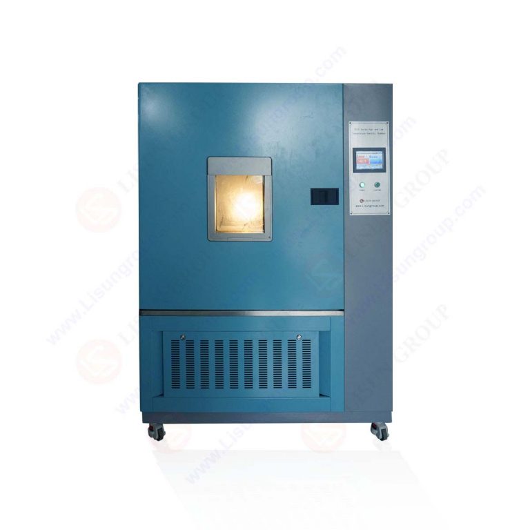
Thermal shock is recommended for:
- New LED die designs or new substrate materials (ceramic vs. FR4).
- Solder joint reliability qualification (e.g., SAC305 vs. lead-free alternatives).
- Automotive headlights which experience rapid thermal transients from cold start to full power.
- Hermeticity testing of ceramic packages.
The LISUN system can be configured for a thermal shock profile with minimal dwell time (e.g., 10 minutes at temperature) and fast transfer (< 30 seconds between chambers).
5.2 When to Use Temperature Cycling
Temperature cycling is recommended for:
- Lumen maintenance validation per IES LM-80 and TM-21.
- Driver circuit reliability testing, especially for electrolytic capacitors.
- Optical material aging (silicone lenses, phosphor layers).
- Life prediction modeling using Arrhenius acceleration.
For this, the LISUN system uses its dual testing modes: a Standard Cycle mode with controlled ramp rates (e.g., 5°C/min) and soak times of 30-90 minutes.
5.3 Combining Both Tests
The most robust qualification plan often involves a matrix of both tests:
- Initial Photometry (LM-79): Measure baseline Luminous Flux and CCT.
- Thermal Shock (10 cycles): Identify infant mortality/mechanical defects.
- Survivor Test (LM-79): Measure flux of surviving units.
- Temperature Cycling (6,000 hours): Run full LM-80/84 protocol on survivors.
- Final Photometry & TM-21: Calculate final L70/L50 projections.
This combined approach ensures the product is both mechanically robust and chemically stable.
6.1 Customizable Hardware Configurations
The LISUN test systems are highly modular. Users can select:
- Number of Channels: From single-channel to multi-channel (10+).
- Temperature Range: Standard (-40°C to +125°C) or extended (-55°C to +150°C) for thermal shock.
- Chamber Size: Small chambers for individual LED modules to walk-in chambers for large luminaires.
- Power Supply Options: Constant current (preferred for LED testing) or constant voltage.
This flexibility allows the same base instrument to perform both thermal shock and temperature cycling by simply changing the chamber profile and fixture setup.
6.2 Software Features for Dual Modes
The LISUN software includes a Test Mode Configuration tab. For thermal shock, the user sets Transfer Time < 30s and Dwell Time = 15 min. For temperature cycling, the user sets Ramp Rate = 5°C/min and Dwell Time = 90 min. The software automatically calculates the correct number of cycles to meet the total test duration (e.g., 6,000 hours). It also logs temperature data from the chamber thermocouple to verify the chamber is meeting the set profile.
6.3 Data Reporting and Compliance
All data is automatically compiled into a report format compliant with IES standards. The report includes:
- Raw lumen maintenance data per sample.
- Average relative luminous flux over time.
- TM-21/TM-28 projected curve with 90% confidence intervals.
- Arrhenius plot showing acceleration factors.
This ensures that tests conducted using the Thermal Shock mode are still recorded within the framework of lumen maintenance, even though the primary failure mode is mechanical.
7.1 Comparison Table: Thermal Shock vs. Temperature Cycling
| Parameter | Thermal Shock | Temperature Cycling |
|---|---|---|
| Ramp Rate | > 30°C/min | 1-15°C/min |
| Dwell Time | Short (5-15 min) | Long (30-180 min) |
| Primary Stress | Mechanical (CTE mismatch) | Chemical/ Thermal (Arrhenius) |
| Failure Mode | Catastrophic (Die crack, bond wire) | Gradual (Lumen depreciation) |
| Test Duration (Typical) | 100-500 cycles | 6,000 hours (continuous) |
| Prediction Model | Weibull (Life) | TM-21 / TM-28 (L70) |
| LISUN System | Both LEDLM-80PL & 84PL | LEDLM-80PL & 84PL (primary) |
7.2 Interpreting Test Results
When analyzing data from a LISUN system, look for the inflection point. In temperature cycling, the curve is smooth. In thermal shock, you may see a sudden drop at cycle 50 or 100, indicating a mechanical failure. The software can flag such events as Catastrophic Failure and exclude them from the TM-21 projection, providing a clearer picture of the remaining population’s chemical degradation rate.
The selection between thermal shock and temperature cycling is not arbitrary but is dictated by the specific reliability goals of the LED product validation plan. While thermal shock targets mechanical integrity through rapid temperature transitions, temperature cycling focuses on chemical stability and lumen maintenance over prolonged thermal exposure. As we have explored, the LISUN LEDLM-80PL and LEDLM-84PL systems provide the dual capability to execute both tests with precision, adhering to IES LM-80, LM-84, TM-21, and TM-28 standards. The integration of Arrhenius modeling within the software allows engineers to extract maximum value from 6,000-hour test durations by accurately projecting L70 and L50 lifetimes. By leveraging the customizable hardware and data analysis features of LISUN instrumentation, manufacturers can ensure their products withstand both the mechanical shock of sudden temperature changes and the chemical wear of long-term thermal cycling. Ultimately, a balanced testing regimen that incorporates both methods delivers a more comprehensive and reliable product to the market.
Q1: Can the same LISUN system perform both Thermal Shock and Temperature Cycling?
A: Yes, the LISUN LEDLM-80PL and LEDLM-84PL are designed with dual testing modes. While they are primarily optimized for long-duration temperature cycling per IES LM-80, they can be configured for thermal shock profiles. The key is in the software settings: you set a fast ramp rate (the chamber’s maximum rate) and a very short dwell time. However, for true thermal shock testing requiring transfer times under 10 seconds between two separate temperature zones, you may need an additional thermal shock chamber. The LISUN system excels at correlating thermal cycling data with TM-21 projections, which is the primary focus of LED reliability testing.
Q2: How does the Arrhenius model in LISUN software handle data from a Thermal Shock test?
A: The Arrhenius model is designed for chemical reaction rates (lumen depreciation) and is less accurate for mechanical failure prediction from thermal shock. The LISUN software applies the Arrhenius model only to the temperature cycling data points. When a thermal shock test is performed, the software logs the data but may exclude it from the primary TM-21 extrapolation. Instead, it applies a Weibull analysis for time-to-failure data from mechanical breakdowns. The software can generate two separate reports: one for L70/L50 projection (from cycling) and one for survival probability (from shock).
Q3: What is the minimum recommended number of samples for a 6,000-hour test using the LISUN system?
A: According to IES LM-80, a minimum of 20 samples per test condition is required for statistical validity. The LISUN systems are designed to handle this easily, with support for up to 3 connected temperature chambers, each capable of holding dozens of LED modules depending on size. For thermal shock tests, which are often more destructive, starting with 30-40 samples per group is recommended to account for early failures. The system’s software can manage multiple sample groups simultaneously, automatically tracking the performance of each individual LED module.
Q4: How does the LISUN system ensure accurate temperature measurement during testing?
A: The system uses T-type thermocouples attached directly to the LED case temperature point (Tsp) as defined by IES LM-80. These are connected to the chamber’s control loop, but also logged independently by the LISUN data acquisition unit. The software monitors the temperature data in real-time, alerting the user if a chamber deviates by more than ±2°C from the set point. This ensures that both thermal shock (which requires precise temperature extremes) and temperature cycling (which requires precise soak temperature) profiles are strictly maintained.
Q5: What is the difference in typical output data when comparing L70 from a TM-21 test vs. a thermal shock test?
A: A TM-21 test (temperature cycling) will yield a smooth, projected L70 value (e.g., L70 = 50,000 hours) based on the exponential decay of the data. A thermal shock test will not produce a meaningful L70 value because the failure mode is not a smooth depreciation; it is a sudden catastrophic failure. The output from a thermal shock test is typically a number of cycles to failure (e.g., 95% of samples survived 100 cycles). The LISUN system clearly distinguishes these outputs in its report, preventing users from incorrectly applying TM-21 projections to thermal shock data.