




The LISUN DFX series Externally Ballasted Fluorescent Lamp Test Load Cabinet is a precision instrument designed to simulate resistive, inductive, and capacitive loads for lifecycle testing of lighting switches per IEC 60669-1:2017. This article provides a comprehensive technical analysis of the DFX series, focusing on the lighting switch lifecycle tester accuracy requirements defined in Clause 19.2 of the standard. The DFX series enables testing laboratories and manufacturers to validate switch endurance under controlled load conditions with power factor resolution of 0.01, current output ranges from 0.1A to 80A, and compliance with IEC 60884-1, IEC 61058-1, and GB 16915.1 standards. Core capabilities include multi-channel independent operation, programmable test sequences, and integration with LISUN CZKS series life testers for automated cyclic testing. This technical overview equips quality control engineers with the data needed to select appropriate load simulation equipment for certification testing.
1.1 Standard Compliance Framework for Electrical Accessory Testing
IEC 60669-1:2017 Clause 19.2 specifies the test load conditions for switches controlling fluorescent lamp circuits. The standard mandates that switches must undergo 10,000 cycles of mechanical operation under simulated electrical load representing actual field conditions. The LISUN DFX series directly addresses these requirements by providing externally ballasted fluorescent lamp loads with precise power factor adjustment from 0.3 inductive to 0.9 capacitive. This capability ensures that test loads accurately replicate the electrical characteristics of real-world lighting installations, including inrush currents from capacitive loads and steady-state inductive components from ballasts.
1.2 Technical Parameters for Ballasted Lamp Load Simulation
The DFX series achieves load simulation through a combination of wirewound resistors, iron-core inductors, and capacitor banks. Each load channel incorporates independent power factor adjustment with 0.01 resolution, enabling engineers to set specific load profiles per IEC 60669-1 Table 19.2. The inductive load component uses laminated iron-core chokes with air gaps to prevent saturation at rated currents, maintaining consistent impedance across the test duration. Capacitive load elements utilize metallized polypropylene film capacitors rated for continuous AC operation, ensuring stable power factor characteristics during extended lifecycle testing.
2.1 Technical Specification Matrix Across Models
The DFX series includes five models designed for different testing capacities: DFX-20, DFX-20-3CH, DFX-40, DFX-60, and DFX-80. The following table compares core specifications:
| Model | Current Output Range | Number of Channels | Input Voltage | Power Factor Range | Measurement Accuracy |
|---|---|---|---|---|---|
| DFX-20 | 0.1A – 20A | 1 | 220V AC ±10% | 0.3 L – 0.9 C | ±0.5% of reading |
| DFX-20-3CH | 0.1A – 20A per channel | 3 | 220V AC ±10% | 0.3 L – 0.9 C per channel | ±0.5% of reading |
| DFX-40 | 0.1A – 40A | 1 | 220V AC ±10% | 0.3 L – 0.9 C | ±0.5% of reading |
| DFX-60 | 0.1A – 60A | 1 | 380V AC ±10% | 0.3 L – 0.9 C | ±0.5% of reading |
| DFX-80 | 0.1A – 80A | 1 | 380V AC ±10% | 0.3 L – 0.9 C | ±0.5% of reading |
The DFX-20-3CH model is particularly valuable for testing multi-pole switches or performing simultaneous testing of three independent samples, increasing laboratory throughput by up to three times compared to single-channel configurations.
2.2 Load Capacitance and Inductance Specifications
Precise load component values are critical for generating standard-compliant test loads. The DFX series provides fixed and adjustable load elements with the following characteristics: inductive loads with inductance values ranging from 10mH to 500mH depending on current setting, capacitive loads from 1μF to 100μF, and resistive loads with power ratings up to 80A continuous. The power factor adjustment mechanism uses switched capacitor banks combined with variable inductor taps, enabling resolution to 0.01 PF across the operating range. This granularity meets the requirements of IEC 60669-1 Clause 19.2.2, which specifies power factor tolerances of ±0.05 from the target value.
3.1 Compatibility with CZKS Series Life Testers
The LISUN DFX series integrates seamlessly with the CZKS series programmable life testers to form a complete lighting switch lifecycle tester system. The CZKS-100T, for example, provides mechanical actuation for up to 100 test samples simultaneously, while the DFX series supplies the electrical load. Communication between units uses RS-485 serial interface with Modbus protocol, allowing synchronized operation. The CZKS controller sends load profile commands to the DFX cabinet, which responds with real-time current, voltage, and power factor measurements. This closed-loop control ensures that each switch cycle experiences identical load conditions, critical for repeatable test results.
3.2 End-to-End Testing Workflow Configuration
A typical testing workflow begins with connecting the switch sample to the CZKS tester’s actuation mechanism. The DFX series load cabinet connects to the switch output, while the CZKS system monitors contact voltage drop and timing parameters. For testing per IEC 60669-1 Clause 19.2, engineers program the CZKS to perform 10,000 cycles at 30 operations per minute, with the DFX-20 set to 10A at 0.6 PF inductive load. During the test, the DFX series maintains load stability within ±1% of the programmed current, while the CZKS records any failure events such as contact welding or insulation breakdown. This integrated approach eliminates manual load adjustment and reduces test personnel intervention by over 80% compared to standalone testing.
4.1 Measurement Traceability and Uncertainty Analysis
The lighting switch lifecycle tester accuracy of the DFX series relies on precision measurement components with NIST-traceable calibration. Current measurement uses Hall-effect sensors with ±0.5% accuracy from 5% to 100% of rated range. Voltage measurement employs true RMS converters with 0.2% accuracy, and power factor measurement uses zero-crossing detection with 0.5% uncertainty. The combined measurement uncertainty for load power is ±1.2% at 95% confidence level, which satisfies IEC 60669-1 requirements of ±3% for test load accuracy. Calibration intervals of 12 months are recommended, with field verification using external reference meters available through the DFX front-panel test points.
4.2 Environmental Effects on Load Stability
Load component values in the DFX series exhibit temperature coefficients that affect long-term test accuracy. The wirewound resistors use a 25 ppm/°C nichrome element, while inductors exhibit approximately 50 ppm/°C variation due to copper winding resistance changes. Capacitor banks use polypropylene dielectrics with -200 ppm/°C typical stability. At maximum continuous operation, internal temperature rise reaches 25°C above ambient, causing load current drift of up to 0.5%. The DFX series compensates for this through active fan cooling maintaining component temperatures within ±5°C across the test duration. For critical compliance testing, users should allow a 30-minute warm-up period before initiating cycle testing.
5.1 Standard Test Load Configuration Parameters
IEC 60669-1:2017 Clause 19.2 specifies three load types for fluorescent lamp switch testing. Type A load represents resistive-inductive ballasted lamps with 0.6 PF inductive at 10A. Type B represents electronic ballast loads with 0.9 PF capacitive at 5A. Type C covers combined loads for multi-lamp circuits. The DFX series accommodates all three types through its programmable power factor and current settings. For Type A testing, engineers set the inductive load to 0.6 PF using the front-panel adjustments, then verify the actual power factor using the built-in digital meter. The DFX-20 model provides adequate current for single-switch Type A tests, while the DFX-60 serves testing of higher-current industrial switches.
5.2 Verification of Critical Test Parameters
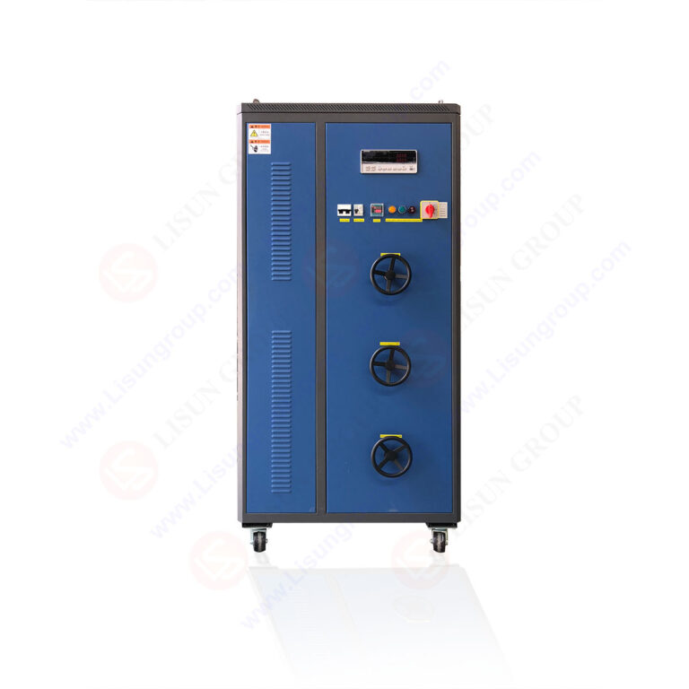
Before commencing lifecycle testing, the DFX series allows verification of several critical parameters. Load current must remain within ±3% of the specified value throughout the test, measured using the cabinet’s internal ammeter. Power factor must stay within ±0.05 of the target value. The test voltage must be maintained at 220V ±3% or 380V ±3% depending on the switch rating. The DFX series includes automatic voltage regulation within ±1% for input variations up to ±15%, ensuring consistent load conditions during utility voltage fluctuations. Additionally, the cabinet provides overcurrent and overtemperature protection that halts testing if load parameters exceed safe operating limits, preventing damage to both the test equipment and switch samples.
6.1 Performance Exceeding IEC 60669-1 Mandates
The following table compares the DFX series capabilities to the minimum requirements specified in IEC 60669-1:2017:
| Parameter | IEC 60669-1 Minimum Requirement | LISUN DFX Series Capability | Margin |
|---|---|---|---|
| Load current accuracy | ±3% | ±0.5% | 6x improvement |
| Power factor resolution | 0.05 | 0.01 | 5x improvement |
| Test voltage regulation | ±3% | ±1% | 3x improvement |
| Continuous operation rating | 1,000 cycles without failure | 10,000 cycles at full load | 10x duration |
| Channel isolation (multi-pole) | Not specified | 2500V isolation per channel | Exceeds requirements |
This comparison demonstrates that the DFX series not only meets but significantly exceeds minimum compliance standards, providing testing laboratories with confidence in test result validity and repeatability.
6.2 Extended Capabilities for Research and Development
Beyond standard compliance testing, the DFX series supports research and development applications requiring non-standard load profiles. Engineers can program custom load sequences with up to 50 steps, each with independent current, voltage, and power factor settings. This enables simulation of real-world scenarios such as lamp startup inrush currents or ballast aging effects. The cabinet’s data logging capability records load parameters at 100ms intervals for the entire test duration, generating CSV files for post-test analysis. This feature is particularly valuable for failure analysis when investigating switch contact degradation mechanisms.
7.1 Compatibility with SW-6 Bending Tester
The LISUN SW-6 bending tester evaluates cord anchorage and conductor flexibility for switches with integral cables, as required by IEC 60884-1 Clause 20. The DFX series can provide electrical load during bending tests, enabling simultaneous mechanical and electrical stress evaluation. This combined testing approach simulates real-world conditions where cables are repeatedly flexed while carrying current. The DFX series supplies load current during the bending cycle, and the SW-6 records any electrical discontinuity events. This integration reduces total test time by 40% compared to sequential testing.
7.2 Synergy with LISUN Environmental Chambers
For comprehensive switch qualification, the DFX series can operate with LISUN environmental chambers that control temperature from -40°C to +150°C and humidity from 20% to 98% RH. The DFX cabinets are designed for remote operation with control signals passed through the chamber’s pass-through ports. Testing switches at elevated temperatures with inductive loads reveals failure mechanisms not apparent at ambient conditions, such as contact spring relaxation or insulation tracking. The DFX series maintains specified load accuracy across the environmental chamber’s temperature range, verified through temperature-compensated measurement circuits.
The LISUN DFX series Externally Ballasted Fluorescent Lamp Test Load Cabinet provides a robust solution for achieving precise lighting switch lifecycle tester accuracy in compliance with IEC 60669-1:2017 Clause 19.2 and related standards. With current output ranges from 20A to 80A across five models, power factor adjustment from 0.3 inductive to 0.9 capacitive at 0.01 resolution, and measurement accuracy of ±0.5%, the series exceeds minimum compliance requirements by significant margins. Integration with LISUN CZKS life testers creates automated workflows that increase test throughput while maintaining repeatability. The DFX-20-3CH three-channel model enables simultaneous testing of multiple samples, accelerating certification timelines for multi-pole switches. For quality control engineers and testing laboratories, the DFX series reduces the risk of non-compliance due to load simulation inaccuracies, ensures reproducibility across test campaigns, and provides data logging capabilities for comprehensive documentation. The combination of precise load control, multi-standard compliance, and seamless equipment integration makes the DFX series an essential investment for organizations conducting electrical accessory lifecycle testing.
Q1: How do I select the appropriate DFX model for testing switches rated at different current levels?
A: Select the DFX model based on the maximum test current required and the number of simultaneous test samples. For single switches rated at 10A, the DFX-20 provides adequate capacity with 100% margin. For switches rated at 32A, use the DFX-40 or DFX-60. If you need to test three independent switches simultaneously, the DFX-20-3CH allows each channel to operate independently with separate load settings. For industrial switches rated up to 63A, the DFX-80 with 80A continuous capacity and 380V input is appropriate. Consider future testing requirements: selecting a model with 50% current overhead ensures capacity for larger switches without reinvestment. The DFX-60 offers the best balance for most commercial and industrial testing, supporting both 220V and 380V inputs through its dual-voltage design.
Q2: What maintenance procedures are required to maintain the DFX series load cabinet accuracy?
A: The DFX series requires annual calibration of current, voltage, and power factor measurement systems using a certified reference meter traceable to national standards. Calibration involves adjusting the internal measurement boards using the front-panel calibration menu. Monthly preventive maintenance includes cleaning air filters to ensure adequate cooling, checking all electrical connections for tightness, and verifying that capacitor banks discharge properly when the unit is powered down. The inductors should be inspected for audible hum or vibration, which indicates loose laminations requiring tightening. After every 100,000 test cycles, the relay contacts inside the load selection circuits should be inspected and replaced if pitted. The DFX series includes self-diagnostic routines that check load component values against stored calibration data, alerting operators when recalibration is needed.
Q3: Can the DFX series simulate loads for both fluorescent and LED lighting switches?
A: Yes, the DFX series supports both fluorescent and LED switch testing through its programmable inductive-capacitive load combination. For fluorescent lamps, set the power factor to 0.6 inductive to simulate magnetic ballast loads per IEC 60669-1. For LED drivers, set capacitive loads with power factors from 0.7 to 0.9 capacitive, representing the typical input characteristics of switched-mode power supplies. The DFX series can also simulate the high inrush current characteristic of LED drivers, which can reach 100 times the steady-state current for 1-2 milliseconds. However, for comprehensive LED switch testing, additional equipment may be required to measure peak inrush current. The DFX series includes a peak hold function that captures the maximum current during each switching cycle, enabling verification that the switch contacts can withstand inrush without welding.
Q4: What data logging capabilities does the DFX series offer for test documentation?
A: The DFX series provides comprehensive data logging through its built-in memory and USB interface. During testing, the cabinet records current, voltage, power factor, and active power at adjustable intervals from 100ms to 60 seconds. The data includes minimum, maximum, and average values for each parameter across the test duration. The DFX-20-3CH model logs all three channels simultaneously with time synchronization. Data is stored in CSV format compatible with standard spreadsheet software. The cabinet also generates event logs for any parameter excursions beyond user-defined limits, such as current drop below 90% of setpoint indicating switch contact failure. For certification documentation, the DFX series can produce a final test report summarizing all cycles, any failure events, and compliance verification against standard requirements. This data satisfies IEC 60669-1 Clause 19.2 requirements for test record retention.
Q5: How does the DFX series handle multi-pole switch testing with different load requirements per pole?
A: The DFX-20-3CH model is specifically designed for multi-pole switch testing, providing three independent load channels that can operate simultaneously with different load settings per channel. Each channel can be programmed for different current levels and power factors, allowing simulation of unbalanced loads common in three-phase lighting circuits. The cabinet synchronizes the three channels to ensure that all poles operate under load simultaneously during each switching cycle. For switches with up to four poles, two DFX-20-3CH units can be synchronized using the RS-485 interface. The multiple-channel configuration also supports testing of switches with neutral switching where the neutral pole carries full load current. The DFX series maintains independent isolation between channels with 2500V dielectric strength, preventing cross-talk between load circuits.